Ricci
-
Posts
1,950 -
Joined
-
Last visited
-
Days Won
357
Content Type
Profiles
Forums
Blogs
Gallery
Downloads
Articles
Media Demo
Events
Everything posted by Ricci
-
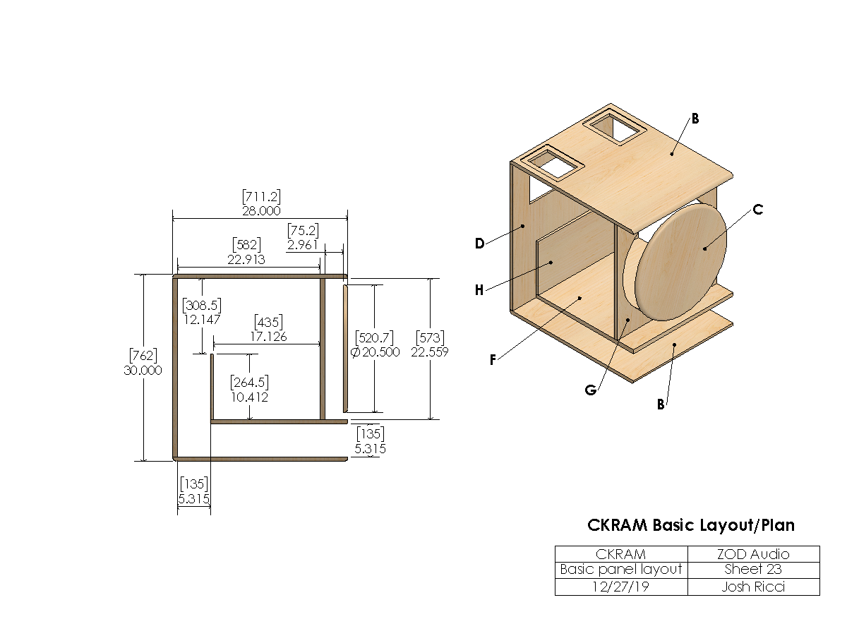
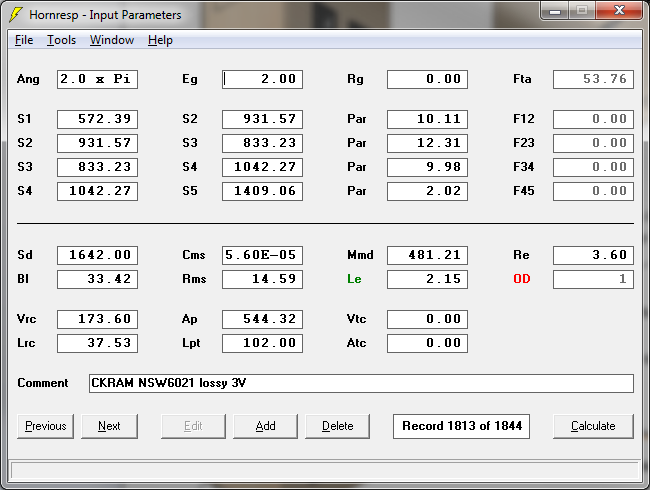
This question has a rather complicated and long answer. The simplest way I can explain it is that the S1 value is the minimum cross sectional area of the air volume in front of the driver cone at the center dust-cap. Technically there really isn't an S1 as typically defined since the driver radiation expands in 360 deg in that axis. The driver is placed in an OD rather than ND arrangement but the exit is closer to an ND arrangement. In some ways it is also similar to a traditional ported bandpass chamber. I modeled it all three ways and surprisingly there is little difference between them. Mostly due to the very limited size and "tuning" being well out of the sub band. The S2 is the area of a circular cross section centered at the cone / dust-cap joint. S3 is the minimum area of any circular cross section seen by the driver as the output is considered to expand from a central point. S4 is the area at the point that the bracing and support structures end. S5 is the area of all exits at the outer surface including the round over. All distances are actual from measurements inside the model. I design backwards from most. After a preliminary rough sim that gives something to aim for in about the size that is available to work with, I design the speaker. The initial sim part is quick and easy. The physical design of the speaker drives the inputs back into the simulation after this. This is a much more difficult much longer process. The dimensions, sketching and values derived are all done by 3D modeling and analysis. It's an iterative feedback looped process until a final design is completed.
-
I wish we were closer I'd take you up on that! Especially after seeing those shop pics. Honestly I have a lot of educated guesses about the top end behavior of the front section but little in real data. It should be predictable in the bass range. Outside of that who knows...Disc diameter is 20.5" so there shouldn't be any cancellation issues until well outside of the sub range. Here's a couple of FR images. Akabak sim with the front section separated into 8 waveguides each with 12 or so segments and the 4 vents all modeled separately. The comparison FR is from HR. The two are really close other than Akabak exaggerating the resonances up top quite a bit. It'll be closer to HR in reality. Driver is the NSW6021-6. Here is the HR response with and without the Edge data added. 2 volts at 1m in halfspace sim. Vent tuning comparison. Driver Comparison. NSW6021-6, SAN214.50. 21DS115-4, 21IPAL.


-
The JBL, Martin Audio, or Harman Curve may not be a bad place to start. These are all similar in general trend to the L-Acoustics graph already posted. Some are more aggressive than others. I usually end up settling somewhere similar in shape with my systems. Gentle rise from the HF towards the midbass that continues on into the bass range.
-
Awesome! Already ahead of the game. Is that your shop? I'm jealous of the tools and space. I have nothing like that.
-
It may be relatively flat down to 5Hz. Can't say for sure without measurements. Curious that the spec is 30-20kHz though. If it was 20-20kHz I wouldn't question it, but 30Hz is a bit odd for an electronic component, which is why it stuck out to me. I wonder if it changes with input pad? I avoid cal files as much as possible for a measurement rig. Especially if big corrections are needed. They are a necessary evil sometimes though. Good luck. Post a frequency response if you get a chance to take one.
-
Hmmm. Interesting. Frequency response spec looks not so great though.
-
Correct the SP amps are already full bridge. So are Inuke6000 and NX6000 amps which is why they can't be bridged again. Most amps are half bridged. Half bridged Class D SMPS amps can get some bus pumping going on when used with HEAVY bass content. Not talking rock n roll kick drum here...Think sine wave sweeps, possibly some ULF HT type stuff. I like to use full bridged operation into subs when possible. In reality with normal content it may never be an issue. Voltage limit on the SP amps is about 126 volts (178 volts peak)
-
Thanks for what you do buddy.
-
I just skimmed this thread trying to catch up on everything I've missed in the last couple weeks, but I have to echo Peniku8 for the most part. I finally finished and posted my "small" 21" design earlier today. It is still significantly bigger than the dimensions you have proposed. Have a look at how the front section was done. I don't think you can shrink it any smaller than that without major performance impacts. The simple slot that was posted above by Peniku8 is the other option for keeping it as small as possible but has some limitations also. The back chamber and ports I could shrink some more but only enough to get another few inches off of one dimension of the cabinet and that comes with compromises. The other option is to increase the tuning frequency. 30Hz + 21" driver starts to limit how far things can be shrunk. As a rule of thumb you will lose about 25 to 30% of your gross volume to bracing, cabinet walls, driver, wiring, etc... 60cm(wide)x68cm(high)x62cm(deep = 253L external volume for the subwoofer. I loaded your simulation data into HR and it says the system volume is 265L (Look under schematic diagram). Based on having 253L external volume available and factoring in the minimum 25% or so that you will lose to driver, bracing etc...results in about 190L best case for your subs net volume based on those outer dimensions. That's a long way off. My "small" CKRAM sub is 61 x 71.1 x 76.2 cm (330L) and results in a net volume of 257L. As far as air velocities go the lower the better of course. Port velocities almost always get high. This is almost always compromised. The horn or slot section can be kept much lower usually. Port compression starts kicking in a lot earlier than most people think. There's already some happening by 10ms. It gets progressively worse from there as does air noises. For the horn / slot section I try to stay below 15ms worst case with the amp I'll be using and <10ms is preferable. With the bass section ports this is almost impossible. I just try to keep it as low as I can, but it's always way more than ideal. I'd have to agree that you'll need to increase the cabinet size significantly or stick with a regular vented cab design. The cab size you've proposed will be tight even for a regular vented option tuned to 30Hz. I'm not trying to discourage you at all! Just trying to help you out.
-
Hey man. Nice looking build. I'm way behind and catching up around here. I like the method of shaping the ports and combating turbulence. The very first thing that I see though is wasted volume inside of the "toilet seat" (LOL...Can't unsee that now!). That volume could be used for the chamber or even the ports. You could knock a big hole or 2 through the bottom panel of the chamber into the toilet bowl area and get that volume back for the main chamber. Every little bit helps. Doesn't have to be pretty. No one will ever see that.
-
Great work! Looks like you are putting together a quality first build. My first couple builds way back did not look this good.
-
Hey Jay. I really think it depends on your preferences, the environment and the content. What sounds good with rock or country outdoors might not sound so great with EDM in a small venue. I'd recommend to start with something relatively flat from 30-100Hz to start and flavor it to your preference over time. If you keep track of it well you may even end up with different presets depending on the musical style or the size of the venue / outdoors.
-
Design Notes/Goals: I started on the CKRAM long ago and got about 85% done before hitting a crossroads of analysis paralysis. I left the project in the dust and got busy with other things for a long time. After I picked it back up towards the end of last year I made some progress towards getting it finalized but was still not sure about the choices I'd made. I left it alone again for a few months before pulling it back up last week. At that point I looked at it with a fresh perspective and changed the final design to what has been posted here. The original goals for this stem back to the dual driver SKHORN design. As soon as it was finished a single driver version was planned, but simply cutting the SKHORN in half was never an option for me. What is a nice, well braced , symmetric layout in the SKHORN is not so pretty once the cab is cut in half. That meant a totally new design was needed. Something the size of half of a SKHORN is quite small for a 21" design. I've always found that the smaller the design is the larger and more impactful the tradeoffs become. It doesn't help that I'm overly analytical and obsessive. I quickly reached a crossroads with the design where I had a few paths to take and didn't really like any of them. At that point I designed the SKRAM instead which was easier due to a bit of extra cabinet size to work with which made it easier to fit everything together. The SKRAM was actually how I wanted the smaller half-SKHORN layout to be but I just couldn't get it to fit in the size I wanted without compromises that were too much for me. I scaled it up to a size that would work well and that became the SKRAM. Eventually I came back to the smaller, unfinished half-SKHORN design to have a fresh look at it and the design goals. I started with what I considered to be concrete design restrictions and a second wish list of design wants. This is all in addition to the usual goals of smooth FR, low distortion, smooth GD, efficiency, power handling, etc. Concrete design considerations... 1.) 12cu ft external or smaller. 2.) Variable vent tuning 3.) 30Hz tuning with all vents open 4.) Single 21" driver 5.) Room for plate amp, handles, casters, feet, stack lugs, pole mounts as needed. "Wish" list in no particular order... 1.) Maximize vent/slot/horn area / minimize air velocity 2.) Straight vent / slot / horn 3.) Thorough bracing / Keep cabinet vibration low especially around the driver 4.) Horizontal driver / Driver stays horizontal regardless of sub orientation 5.) Symmetric loading on the driver cone 6.) Works well with a variety of drivers 7.) Keep construction simple 8.) Minimize weight 9.) Minimize direct sound and operational noises from the driver. If you read through the 2 lists above it becomes apparent that some of these are at cross purposes. There is no way to achieve everything without compromise. Do you maximize vent area, or keep a straight vent? More bracing to make sure the cab is dead vs less weight and build complexity? Eventually I prioritized a few things more than others and got to a place that I thought was a reasonable set of compromises for a sub this size. The major design considerations all had to do with the front section of the drivers output. Since the sub design had to shrink so much space for everything is at a premium. I knew that the back chamber air volume would be at a premium. I decided to shrink the front volume as much as possible while still achieving something useful. I quickly realized that I would not be able to do a proper "horn" section like the SKHORN and SKRAM subs due to the space premium. I looked at straight slots and expanding vs contracting. The physical size of the driver was setting limits on the size of the slots and the air speeds due to the reduced area were getting higher than I would like. They also put the driver into orientations that were not ideal. Eventually I settled something more similar to a BP chamber than a horn or slot. It had the advantage of keeping the driver horizontal and placing the output radiators symmetric about the center of the cone, which should result in a more even pressure distribution on the cone. It also shortens the average path length for the driver energy to exit but also allowed a larger, quicker expanding area at the exit. At first I was going to use rectangular or triangle corner exits. Before deciding on a circular / triangular profile. At that point I was almost done with the design and had settled on this arrangement for the front section. It was at this point that I started to think about going from a hatch system with internal driver to a removable front section with a standard front mounted driver. Originally I had a hatch for driver access and the front section was non removable and solidly attached to the rest of the cab. It would've worked but the hatch was a very tight fit and it compromised the bracing in the center of the cab and complicated things. Positives for moving to a removable front assembly were: The driver hatch could be eliminated, which simplified the internals and bracing. Driver access would be easier. Also the cab could be run in a normal vented configuration without the front assembly. Negatives were that it complicated the front assembly, reduced the driver excursion clearance somewhat and reduced the size of the bracing and possibly the solidity of the front section. I decided the positives outweighed the negatives so the design was updated one more time to what is seen here. This cab is 24x28x30" which is quite small for a 21" design. It is actually slightly smaller than a half of a SKHORN but the design ended up much different. For comparison an Othorn is 24x36x36 and a SKRAM is 24x32x36. This cab shaves 4" off of the depth and 6" off of the height compared to a SKRAM and does so with a significant weight savings as well. HIL is always in effect so this cab does give up efficiency & sensitivity to the larger SKRAM and OTHORN cabs. There is simply no way around that. I chose to focus most of the CKRAM performance into the deep bass rather than using the front volume to turbo charge the mid and upper bandwidth like with the SKHORN and SKRAM. The gain of the front volume is probably only going to be 1 or maybe 2dB compared to a regular vented cab if I get lucky. Testing with and without the front assembly should be interesting. This tradeoff was acceptable to me in order to keep smooth response and powerful output in the deep bass from a cab this size.
-
Here are the print files. As usual 18mm and 12mm, void free BB ply is recommended. Can be built with or without CNC. CNC programming will have to be developed on a case by case basis for your shop/machines/software. Modify as needed for your situation. The basic dimensions and overall layout are what is critical. The hardware, assembly, materials and other processes can and should should be adjusted to suit the situation. For example the front panel assembly that covers the driver should be modified if cut on a CNC for the inner disc and outer round panel to "lock" the braces into place and screws should be used along with glue. Free use of the plans to build subs for yourself is fine. Use of them to make a finished commercially sold product is not. NOTE about the prints! These are extremely detailed due to being designed in Solidworks and the plans from which my personal cabs would be built. The simplified layout drawing is really all that should be adhered to to build this sub. The bracing and front panel assembly can be simplified to suite your own ideas or the tools available to build the cabs. Just make sure it is solid! Any or all of the hardware can be deleted or substituted or modified to suite your needs. Think of the plans as a chassis guideline that can be modified to taste. You don't have to put the holes in your braces or use the handles, a roundover on the cab edges, add a cutout for a plate amp, etc... DXF's will be added later... CKRAM print.pdf
-
The CKRAM is a compact, single 21" subwoofer, that is designed to be flexible enough to suit a variety of applications, but is primarily intended for sound reinforcement or Pro use. Dimensions: (24" / 610mm) Width x (30" / 762mm) Height x (28" / 711mm) Depth Drivers: Most of the good pro audio 21" drivers will work well in this cab. The Lavoce SAN214.50 is a good budget option. The Eminence NSW6021-6 is what the CKRAM was designed with during modeling. It or the B&C 21Ipal are top tier options. Other drivers that should work well include 18 Sound 21NLW9601, 21ID, B&C 21SW152, 21DS115, etc... Design: The CKRAM is a hybrid 6th order design in some ways similar to the SKHORN and SKRAM designs but notably different in others. The CKRAM has a multi-port back section which allows for adjustment of the port tuning to suite the application. The front section is in effect an extremely short, symmetric, horn/slot/small vented chamber. The front assembly is intended to be removable and the CKRAM can also be operated in a standard vented alignment. Vent Tunings: Note that the CKRAM can be operated in 6th order or standard vented operation. In either case the vent tunings remain the same. All vents open = 30Hz 3 vents open = 25Hz 2 vents open = 21Hz 1 vent open = 15Hz Horn Response Models: These should be close. The inputs for each vent configuration are included. The match is quite close to a much more detailed Akabak model. Use the semi inductance specs for the driver you are simulating! NSW6021-6 semi inductance This is the Akabak script if anyone wants to dive that deep. ckcomplx.aks


-
It will be this spring / summer. Last summer there were a number of external forces that conspired to halt testing for 2019. I'm hoping this year I will be able to get more done.
-

Back to Transients. Understanding "Q" and myths of bass.
Ricci replied to Trdat's topic in Speaker Design
SME I think we are on the same page. I was just clarifying what was meant by my comments in the bass myths section. They are primarily addressed at the subjective terms that "audiophiles" & average people throw around about bass and the causes of those terms. Also the trend of visually comparing subwoofer impulse responses. Linking the subjective to the objective is where the fun really is. This is a DEEP subject well beyond the scope of 2 paragraphs in the bass myths article. For example wide range dynamic capability is often overlooked entirely when discussions of transient response, or accuracy arise but it is absolutely critical to good sound. I agree with you. I run 8 sealed RF 19's which loaf along at most any level I care to use in my home. Extension is relatively flat down to the 6Hz range. Electronics roll off starts to stack up below that point. Anyway... I'm familiar with the type of bass reproduction you are describing. Technically and subjectively I agree. With that said the bass systems that we have are the 0.1%. Most people have never heard this type of system. If they have they may not have been able to spend real time to get used to it. When we go back and consider the types of mass produced systems most people have, the rooms, FR's and listeners who use terms like speed, fast, weight, boomy etc in reviews and descriptions and then begin to consider WHY the small sealed subwoofer, or open baffle is often described as "tight" or "fast" while the much bigger, deep tuned vented sub is considered to be more booming and "loose". Objectively the measurements will show that the vented sub would show the smaller sealed sub or OB to be at a large disadvantage in: Distortion, dynamic range capability and deep bass SPL capability, etc...The only clear objective wins for the small sealed sub would typically be well below the vent tuning of the vented sub, lack of vent noises and group delay near the tuning of the vented sub. Some of these may even be questionable advantages depending on the DSP applied to the sealed sub and the particular vented sub in question. The question isn't whether these subjective terms are right or wrong but why / when they are used. My opinion is that it is not directly related to ringing of the vent on the ported sub, or sub or room resonances, etc, in most cases. IMO it primarily has to do with overall bass level, extension and FR shape. It is also my opinion that visually comparing subwoofer impulse responses as a measure of "speed" or "tightness" is worthless unless the impulses are measured with both subs having matching FR and output level. The sub with greater extension and low frequency energy (Better at being a sub!) will show a longer slower impulse measurement. -
That's a nice looking speaker setup. Don't think I'd kick it out of my room.
-
I've been off grid for a few days and trying to catch up...It's been busy here! Looks like new builds are coming from new users. QSC PL380 is a solid amp. My only gripe is it doesn't have the DSP and networking features of a lot of the newer amps. I'd use the 21DS115 or Lavoce SAN214.50 instead of the 21NLW9601 just due to the lower cost and the slightly higher excursion. Nice looking final pics of your cabs Peniku. N8DOGG I'm glad to see you finally finished them. What are you replacing in your room or can you actually fit more subs? Last I heard your room was basically a wall of subs to begin with!
-
Back to Transients. Understanding "Q" and myths of bass.
Ricci replied to Trdat's topic in Speaker Design
You are taking the quote out of context a bit. I think we are talking about 2 different things. Objective signal reproduction capability of the speaker vs subjective perception of the reproduced spectral content. Comparing the technical reproduction of a system that is flat from 0.1-100kHz to one that is sort of flat from 40-15kHz with some resonance issues is a slightly different comparison. Yes technically the wide bandwidth system can better reproduce the input signal (assuming it also has equivalent headroom, dispersion, distortion, yadda yadda) Objectively that is correct however I'd bet that depending on content a large percentage may still pick the more "flawed" less capable system as having tighter or faster bass in a blind comparison. Why is there a common perception that a smaller sealed sub will be tighter or more articulate than a much larger vented sub? This didn't just appear out of nowhere. I don't believe it has to do with ringing of the port either. It has to do with much greater low frequency energy, headroom and extension IMO. Technically and objectively the large ported sub probably has a great advantage at reproducing the signal. My comment is meant to illustrate people's subjective preferences and the fallacies of looking at things like the shortness of an impulse to gauge bass tightness. Bass frequencies are not fast. Low frequency wavelengths are inherently slow by definition. The initial positive pressure and the stop of the signal can be abrupt and fast which is related to ringing, resonance and overall bandwidth and FR but a certain amount of time is required for a frequency to develop and this takes longer as frequency decreases. As deeper frequencies are included in the signal the signal takes longer to complete. How can adding more low frequency extension and energy make the length of the signal faster? Alternatively many people will pick bass response that is boosted some in the 60-150Hz range as tighter. The result is the same. The way something sounds to someone is subjective to them. If you blind test 30 people and start with a system that has extension to 5Hz and content that is full bandwidth and do nothing more than gently roll off the the lowest frequencies ever higher for each test most of the people will not pick the most full bandwidth one as the fastest or tightest sounding. Because it isn't. It contains more of the low frequency energy. It IS slower and thicker sounding. The energy has changed to include more LF's and deeper extension. I've done this test with friends before. -
Looks like fine progress to me. Just take your time with the build (Measure 2 or 3x and cut once!) and apply advice from others who were in your shoes at one time. It's not that difficult. It just takes some experience and elbow grease.
-
I use big chunks of mattress foam to block ports all the time. It works just fine. Yes it is a little bit leaky. No you will not be able to hear or tell a difference. Just make sure it's over sized and stuff it in there. Make sure the general shape is the same as the vent. The pieces I use are about 8" thick. I'd go with a 3rd or 4th order high pass at about 13 or 14Hz. Your electronics chain and amps will add a 1st or second order high pass at around 8Hz to begin with. 48dB is a little excessive but IMO but it won't hurt to try it.
-
Give it a shot. Tuning should be in the 15Hz range. Your sealed will probably only have an advantage below that point. If you went to 4 of them for extra headroom with the lowest tuning I don't think the sealed will have any advantage until very low in frequency. Likely below 13Hz or so. Depending on your room it may be more reasonable to use a tactile transducer setup for the really low stuff rather than throwing piles of sealed subs at it.
-
The newer drivers with higher xmax and lower Qts lend themselves to compact 6th orders better than the drivers of old. IMHO. At least that's how I ended up on these during the MAUL design process back in late 2014. I'd like to think I had a hand in popularizing this type of 6th order among the DIY crowd and perhaps even the pro market (In this case it's probably a result of form following function). Among the DIY scene they sure seem to have exploded in the last year. There's always been 6th order variations going back decades though. Too many variations to count. There really isn't anything new in audio. Just different spins on the tradeoffs and design choices. The only thing I did different was slot load the drivers and shrink the slot or horn greatly compared to the old pro audio designs. The old pro designs used the volume in front of the driver for huge gain in the >60Hz range but the chamber for the "low end" was basically an afterthought and greatly overpowered by the higher tuned section. HIL is always in effect. I also planned to have multiple tuning options for the low section from the get go, which you don't see on the pro 6th orders. I try to get a reasonably smooth and extended response while still picking up a bit of broadband sensitivity vs direct radiating. I also try to keep the resonances under control and bury the driver noises a bit. A lot of the old 6th order designs were notoriously bad and labeled as 1 note, or boomy so I spend most of the effort making sure it will sound good first and then worry about loud second. I did the same with the Othorn TH back in the day. You have to sacrifice some loudness for bandwidth and smoothness. As far as why 6th's seem to be popular and TH's seem to be less so these days, I'd say it is due to the fact that 6th orders can be smaller than a TH to cover the same bandwidth. TH's are also more tricky to design well and build. Especially once you start attempting to tune them much below 30Hz. A good 6th order system can also be tricky to get right though.
-
Thanks for giving a quick review. Good set of notes. Sorry I thought I mentioned leaving the handles off on this page! It is recommended to leave the side handles off until the driver is installed. It helps a lot. Extra space and access to the screws. I always use gasket tape on the handles so they can be easily removed. Gorilla glue!? #5 is DB approved. Not sure about the photo limit. I'll ask about it.