Ricci
-
Posts
1,951 -
Joined
-
Last visited
-
Days Won
357
Content Type
Profiles
Forums
Blogs
Gallery
Downloads
Articles
Media Demo
Events
Everything posted by Ricci
-
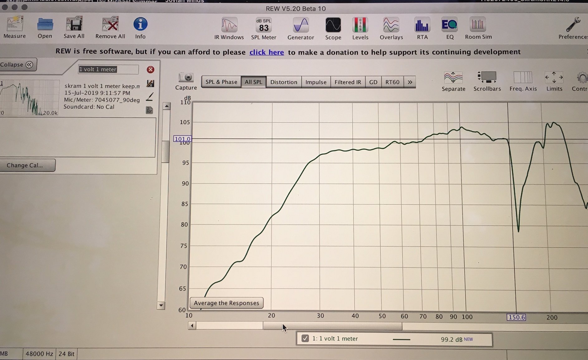
The 85Hz notch is fairly narrow and shallow. it wasn't in the raw measurements so it's likely some sort of artifact or perhaps an unintended EQ band. The port resonance cancellation at 160Hz cannot be filled in. Don't worry about that. If anything you may find that adding a band of EQ to knock that peak at 200Hz down may improve it a bit. The low pass is already pushing it way down in level but it may be worth a shot to knock it back another 10+dB. You may hear a difference or you may not. Response through the bass and mid bass region with the Danley's looks fairly smooth. For music and especially live sound or club work I'd run the bass quite a bit hotter. The crowd always loves the bass. Start with the JBL/Harmon curves and season to taste.
-
Adding 2" of width shouldn't affect things much but I'd not add the height. Can you not lay the subs on their side so they are 36" wide? If you are using more than 4 or more subs you should be able to stack them or arrange side by side for plenty of width.
-
You should use the semi inductance parameters. Green...The Red Le setting is only a best guess for when you do not have better information to go on. I'll go back and look at my Skhorn sim when I get a chance. I've got probably 100 records or more for the Skhorn going back years so it's possible I may have grabbed the wrong one or something.
-
If you have the built in DSP you may as well use it right? Less cables, less pieces to fail. If it does not work for some reason perhaps look into another external DSP box. It cannot hurt to try the Skram's with the tops first. If you think you need the kick bins you can always build some later. Let us know how the material testing with Birch, Poplar, Carbon, Banova goes. I think this will be interesting for many of us.
-
I don't see any issue with modifying the plans a bit for 15mm wood. It should still be strong enough. Banova ply for the interior bracing would be nice as we were just discussing it at AVS but it seems quite expensive. Carbon and epoxy bracing sounds interesting. What's the goal though? Weight savings? I don't generally use kick bins. I like subs that can get up fairly high in frequency and big mains that can get low with power so I don't usually add a third set of cabs. I like to put the extra weight and size of the kick bins into the subs and or mains, and have one less amplifier channel and set of DSP settings to worry about. YMMV. A lot of other guys swear by the kick bin approach. If your preference is for kick bins the Martin 215mk3 design gets a lot of praise but it's bigger and heavier than a Skram so it better be good! It'd be hard for me to pack a pair of those when I could add another <120Hz sub cab instead unless I was already running like 8+ subs. If I were designing a dedicated kick bin I would do a FLH, or plain old bass reflex for sure and not a TH or bandpass variant.
-
That is correct. The relatively shallow 12 and 18dB filters have been adequate with the sine sweeps at max level which start at 2Hz. Also the pro drivers used in these and the Skhorn are VERY resistant to mechanical bottoming. A filter is recommended but there's no need for something like a 36 or 48dB octave slope for protection. I wouldn't go any steeper than 24dB.
-
A pair of Skram's has larger back volume and vent area over a single Skhorn. The cab is just split in half for easier moving and arranging. I'd hesitate to go much bigger / heavier than the Skhorn in a single cab.
-
Do you have the raw measurement with no filters for comparison?
-
NSW6021-6 looks great in either the Skhorn or Skram. No mods needed. Same for the SAN214.50. If you want a larger back chamber use the Skram.
-
Beautiful setup.
-
Yes. These unload below tuning. The only cabs that do not are those with a sealed chamber on one side of the driver, or IB. I use 18dB BW most of the time. 12dB when I can get away with it. I never go any steeper than 24dB. It typically causes greatly increased group delay at the corner and removes any possibility of useful output below tune. Typically there is some useful output till about 1/3rd octave below tuning. Also extremely sharp cutoffs just seem to sound unnatural to me.
-
Use the newest one. The old ones were probably a few iterations back. I've probably got 50+ Skram records with different drivers, vent configs, front chamber configs, alternate cab designs etc. Also when siming cabs you can come up with quite different results based on where you set the section points (S3,S4,etc) and how the throat is simed. The cab hasn't changed the sim inputs have. This is why I usually try to wait until I have measurements to determine the correct HR inputs. Jay's measurements confirmed which way of siming the cab is closest. Even with a lot of previous experience there are times where it's a bit of a guess until it's measured. Like the vent behavior mentioned earlier. This is also why I never assume other peoples cabinets perform like sim'd without seeing measurements to back it up.
-
Where are you located Jay?
-
That's something I haven't considered much. With vents next to the ground this could account for another 2.5 to 3" (7 cm or so) of apparent vent length give or take. That's enough to drop the tune about 1Hz lower. Might be a bit of that going on in Jay's measurement too. That's something that affects any vented or horn cab that radiates next to the ground or a wall. Since these may or may not be arranged with the vents on the floor I wouldn't add it into the sim by default. The internal geometry is always in effect though. I might have some data in the archives that would show this difference in loading the vents but I'd have to dig around. I may not.
-
That looks close to me. 30Hz tuning is what it should be. Real world measurements usually don't show quite as sharply a defined corner, which can make it more difficult to visually pin point the tuning. Looks close to expected though. The maximum port output is usually a little below the low frequency corner of the combined system response. This is due to the output cancellation below tuning which nullifies some of the port energy. Peak airspeed is a little below tuning usually as well. If the measurement is closer to the port than the upper frequency radiator it can show increased low frequency output and a lower corner. This was probably what was happening in the first measurements. I've attached the sim'd response with the 21SW152-4 with semi inductance included. There are 2 traces on the graph because one shows the correct port area and apparent functional length (With the notch at 150Hz) and the other shows the actual straight vent length with adjusted vent area to maintain the correct tuning. I figured the real result would be somewhere between the two but wasn't sure which one it would be closer to. I was hoping it would be closer to the actual vent length with the smoother response above 150Hz, but it seems to be closer to the unadjusted one. It is shifted a bit better than that sim shows though. Notice that the sim rolls off much more abruptly above 120Hz towards the notch. Your measurement shows that the notch due to the pipe resonance and the upper end peaks are shifted up in frequency a little and the response is quite flat up to 150Hz before a much more abrupt notch at the pipe resonance. This is what I wasn't entirely sure about before measuring this one. Basically I was trying to trick the tuning of the ports to be a bit lower than expected so that vent area can be maximized, but also trick the pipe resonance up in frequency a little too. It worked to some extent but I was hoping it might come in a bit higher than it did. Anyway those are a few tricks I tried to use on these. It's the little things that can really be of interest sometimes. @SME As far as calculating vent length for tuning purposes when loading into a wall it's a little bit of calculation and a little bit of art. I've been pretty close on mine so far but perhaps I'm just lucky. On the Skram the back wall actually forms a 90deg bend for the vent so I add in the chord length from the bend through the center section and then the pipe termination only terminates on one side because the other is the back panel so I add an additional half of the vent width (length from center end plane of vent to center-point of a 45deg line sketched from the end of the terminated pipe section to the back wall. It seems to be very close on this one.


-
Looks good. Took you long enough!
-
Hey Jay. Thanks for posting graphs and feedback on yours. Try to limit your graphs to 10Hz-300Hz or something like that and about a 60dB total range of SPL. Anything below about 50 or 60dB is going to be getting into noise floor anyway. You want to focus in on the data of interest on the screen. SME mentioned measuring voltage. That's easy and useful to do. Whenever you setup to measure next time. Run a 60Hz sine wave from REW's generator through the system and measure with a DMM at the speaker terminals. If you are using speakon it's easy as pie just measure at the screws on the connector with the collar pulled back. Mark down your gain setting in REW and save it with the voltage in the measurement notes. You can calculate the voltage based on the gain as long as the gain setting is tracked. The response shape looks good to me. Looks a little bit different above 130Hz than I expected. More rolled off above 130Hz. Do you have a low pass filter engaged? Low frequency corner seems a little lower than expected too. That could be closer proximity to the port than the horn section. Anyway good effort. Can you tell me what frequency the notch is on the top end? 150Hz? Doesn't matter too much but it gives me some data on how the vent resonance behaves. Doesn't really matter since these are subs and look flattish to at least 130Hz or so but I was curious how it would turn out. Vents are using the back wall and have effective length much longer than the physical length. The vent resonance I was hoping would behave closer to the strict physical length than the apparent length but it doesn't seem to have worked quite as well as I'd hoped. Oh well...That's all behavior above 140Hz anyway. I've been very busy so I haven't had too much time to check in around here lately.
-
I posted the possible vent tunings with these a few pages back. With 1 vent open it should be around 14Hz. In a room for HT, with a lot less overall headroom needed than for PA work this might be the ticket. I think 2 vents open was going to be about 19Hz.
-
Brian, Not yet...This is the first design I ever posted prior to doing a GP workup. It'll get there eventually. I don't even have cabs yet and I think it's approaching 10 people who've already built them. Comparisons to vented have been discussed a lot. I'd suggest reading through the Skhorn thread, the M.A.U.L. thread and this one from the beginning. My reasons for using these style of cabs go a little bit beyond simple sensitivity and output gains. The short version is it buries some of the operational junk from a direct radiator in the cab and gets a few more dB before the sound audibly degrades.
-
I don't think the 21SW152 really offers much more excursion than the 9601. Maybe just a bit. Overall they are fairly comparable. Whichever is cheaper should work well. I don't think either would be a noticeable upgrade over the other.
-
I may see about getting the RCF for a next round of 21's, but it will be quite some time. Still no availability of 21TNLW5000 over here. Yes this and the 21IPAL are definitely a cut above any of the other pro 21's I'm aware of. I may try to power a single 21Ipal in the same box with the SP1-6000 for a more direct comparison, but I'm not sure how well even that amp will deal with impedance mins <1ohm during the sine wave sweeps. The K20 did not like bursting into it way back when I tried it. The impedance on the Eminence is a big selling point for me. MUCH easier to power in singles or in pairs. The NSW6021-6 gives up a little bit of motor force to the Ipal but I think I like the mirrored spiders and spacer setup for the suspension better. Hopefully these put other mfg's on notice and inspire more competition.
-
A K10 should be a great match. Any of the big touring amps would be capable. Other options would be Crown Itech-12000 / Itech 4x3500HD / MA-12000, QSC PL380, Speakerpower SP2-8000 / SP2-12000, etc...
-
These 9601's appear to be more similar to the B&C 21SW152 and slightly older generation drivers than the SAN214.50 / 21DS115 drivers. What I mean by that is these are a little bit shorter stroke but with a lot of power handling. Makes sense because these have been around for a while. Good drivers but they do not have much past the 14mm xmax rating. It's much less of an issue once they are put into cabs that limit the excursion like they are intended for. Yes the 21ID is rated at exactly the same xmax and power handling as the 9601 but it appears to have a little bit more of both based on the testing.
-
Thanks for posting this. I was not aware that they had a newer higher power 21. The gaps specs are only slightly different with a 4mm longer gap and only a 0.8mm longer coil. Looks like functional excursion won't be too much greater. Perhaps a mm or so for the new one. It isn't as efficient as the 214.50 but it should have higher power handling. I wonder what the price will be like. Lavoce is an Italian company with R&D done in Italy and China MFG.
-
What driver would you be using? #2. I'm not sure I understand what you are asking? The Skhorn is 54"x32"x24". The front face is 54"x24". It can either be 54" high which would be typical arrangement, or 24" high and 54" wide. The Skram is 36"x32"x24". The front face is 36"x24". Usually it would be 36" high and 24" wide. Either cab can be arranged either way depending on the needs and amount of cabs. PA situations is really what these are meant for first and foremost.