

Droogne
-
Posts
232 -
Joined
-
Last visited
-
Days Won
2
Content Type
Profiles
Forums
Blogs
Gallery
Downloads
Articles
Media Demo
Events
Posts posted by Droogne
-
-
19 hours ago, Ricci said:
I already factored in the extra proximity effect when I made my comments. That panel will need to be about 26cm to get the effective vent length in the sim. Looks like it is about 18 -20cm at most.

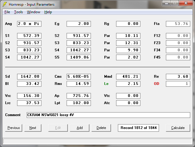
Ok using the port size listed in the post above (793cm²):
- first part of the port (black line) is 65 (the depth) - 1.8 (backpanel) - 15.50 (height of the port) = 47.7cm
- second part (blue line)/the corner = 15.5cm (port height)
- third part (red line) then should be 85cm - 47.7 - 15.5 - 7.75 (50% of port height) = 14.05cm
QuotePort bracing should always be accounted for. It reduces your effective vent area and multiple vents also tune a little higher than one big vent.
How do I take the multiple vents in account? I know I have, but couldnt find out how.
QuoteAt the end of the day we are probably talking a difference of a few Hz difference in the tuning, but even that can make a difference.
I try to get as close as I can.
QuoteS1 starts at the wall where the panels pinch together. Do you have 8 or 9 cm there before getting to the driver?
Parallel wiring with speakons depends...You have a few options. You could make a splitter Y cable and run a speakon to each cab direct from the amp. You can also put 2 jacks on a cab and wire the second jack in parallel and use it to daisy chain to a second cab. This is much more common.
I take 53.5cm into account for the driver surface, so shortest distance is 53.5/2 = 26.75. However, I have placed the driver somewhat more to the left external pannel (pink). This increases S2.
The front horn length: 64.1cm = 85cm - 2* 1.8cm (external pannels) - 1* 1.8cm (pannel between port and horn) - 15.5cm

L12: 35.1cm = (64.1cm / 2) + 3cm
L23: 18.84cm = 64.1cm - 35.1cm (L12) - S3 height (10.15 = S3 area / depth = 573cm²/56.4cm)
L34:
black line: 20.3cm = 10.15*2 (S3 height *2)
red line: 33.65cm = 64.1cm - S3 height - S5 height
L45: 20.32cm = S5 area/depth = 1146cm²/56.4cm
S2 area: 372cm² = (L12 / (L12+L23) ) * S3 area

Based on HR I get a front horn that takes in 71L which seems to fit with a simple check: 64.1cm (length) * 20.3cm (height) * 56.4cm (depth) = 73L
-
MAIN BOX: 284.6L internal
SECOND BOX: 111.24L internal
TOTAL: 395.8L
INTERNAL PANNELS
horn, port: 19.4L
bracing (calculated 10.7L) 15L to give some reserve
DRIVER: 15L
395.8 - 49.2 = 346.64L
HR schematic: 359.5L
So yes, I miss around 13L (with a 880cm x 92.6cm port, which was the adjusted value from te original 922.4 to allow the voume taken in by the port bracing.)
As I want to keep the size the same, and I think I can manage with a smaller port I adjusted to:
793cm² x 85cm which brings the HR calculated volume to 345L.
-
How do you guys wire subwoofers in parallel when using speak on?
-
1 hour ago, peniku8 said:
I'm unsure if the drawing is accurately to scale, but 90cm of port length seems close enough if you add half of the port height.
Correct, is exactly what I did.
QuoteThis is a very large port. I like to have at least 100cm² per litre of displacement. For the 21DS115 that is 5l and I ended up using ~550cm² in a design that prioritized space efficiency. Low port compression is nice and everything, but I'd try to see if more back chamber volume isn't more useful in this case.
I'll double check. However, I still think this is not too much or anything. Especially when you close of a part of the port for differential tuning. Also, when taking the port bracing its more like 850 than 920.
Also, my restrictions were not so much space, rather footprint and carryability. Splitting it in 2 and keeping the footprint between 60x65 does that.
QuoteI also think a meter of port length is quite a lot. A port this long on a 6th order bandpass would have me keep a close eye on group delay for sure.
The SKHorn essentially uses less than half as much port area with 50% more capable drivers and the compression results are very tolerable until output exceeds 130db from 30Hz and up.
True. I modelled based on those results. However, I'll see if I can't make it shorter. Because I need the subs to be 120cm long (as I realised they are perfect speakers stands for my mains) I can't make the subs much smaller. Maybe a better volume vs port size ratio might be good. But the 60x65x120 size is fixed.
QuoteCover the top part of the cab in Warnex inside out so you can use it as transport box for something else 😊
Maybe 😛 but if I want to brace it, that will be somewhat harder.
Maybe I'll open up those second boxes on 2 sides, so I can add more than one box. Interesting.
-
1 hour ago, Ricci said:
A couple of things that I see to double check.
Not sure the horn section has 133cm of length? It's a little hard to judge from the drawing scale. Could be close.
I'll double check. In any case, the length didn't change a lot to the FR/velocities.
QuoteAlso seems like the L12 length of 37cm is possibly a little too long. SKRAM is 28cm.
QuoteIs there an extra 9cm length there? Again hard to tell for sure from the drawing.
S1 does not start at the edge of the woofer, for construction/design reasons.
QuoteI think you may need 2 or 3cm more on the overall height to get the overall volumes in the sim. Depends on bracing, etc... though.
Tomorrow I'll do an exact calculation of the volumes taken in by the bracing. I might add some height. Easy because height isn't so much an issue anymore. Because I split up the sub, I can transport it easily, few cm won't change that.
QuoteVent doesn't look long enough to effectively be 96cm to me? Based on your dims and port area provided the panel that connects at 90deg to the main vent panel would need to be about 26cm long to make a 96cm effective vent length.
As peniku noted, I added 50% of the height, so 13cm/2.
-
(For the LaVoce/DS115 (for example in the future) I would use a somewhat bigger front horn to boost that dip between 50 and 80hz. Would result in around +-1dB extra output in general.)
-
34 minutes ago, peniku8 said:
Designing this thing on paper is pretty hard, I'm sure. Whenever I have a cab idea, I'm putting the whole thing together in Inventor and grab the measurements off the actual model, which I then input into HR. It's a lot of work for a concept which might be really bad, but it leaves very little room for error. This way you can create a very accurate feedback loop to get to the desired result.
I have to admit I have no clue about how to use it. Drawing is pretty easy, and quick. As long as I have a design that doesnt change in the depth, I can do it 2D.
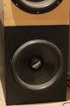
34 minutes ago, peniku8 said:What's the actual frequency response of the cab? Did you find semi inductance parameters somewhere?
I also have to admit I cant find them.. I know it is not ideal, but no way around it. Everything I read is that the NLW9600 is a very good driver.
Normal FR

LaVoce SAN 214.50 with Le activated for reference:


-

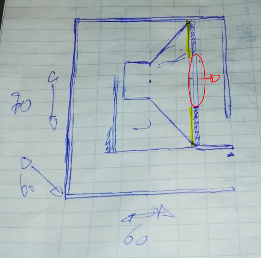
Final design @Ricci @peniku8. EDIT: now with accurate drawing
MAIN BOX
So a 65 (depth) x 60 (width) x 85cm (height) main box, which will accomodate all the vital parts (driver, front horn and port). There is around +10cm of clearance behind the driver. Port in yellow, horn moth opening in green.
SECONDARY BOX
A second box (in yellow) measuring 65 x 60 x35cm to add volume. They are in connection via the vertical red line. This opening will be just as big as it needs to be to insert the driver into the main box. The 2 boxes will be joined together by 8 clamps and a double of layer of sealing material between (to make them airtight, and to make sure they dont rattle).

31hz tune. 350cm² added to S2.


Horn mouth velocity at Xmax limited output at RMS (reduction of the output between 50 and 100hz a reduces it down well below 6m/s).
-
4 hours ago, Ricci said:
Yes.
It's not that the LW1400 would not work, but it would not be my first choice and I would want to be careful with the overall volume until figuring out what it could take.
Well, then I'll build the x2 subs for the NLW9600 and test the LW1400 in it too. Otherwise I could just sell them, or build some sort of cab (with the LW1400) to support the NLW9600.
18 hours ago, Tahoejmfc said:I understand wanting to go smaller on the box design. But after the last 3 weekends using the SKRAM with a B&C 21SW152 4ohm and a QSC PL380, I'm convinced that lugging around the box is well worth the output the original SKRAM design puts out. It is heavy yes... it take 2 people to load it onto a snowmobile deck on my truck, yes.... it takes up alot of space in my garage for storage, yes.... but when you crank it up with some Meyer Sound UPJ's, its worth the tried and tested design that Ricci put a ton of time into designing.
If you have a alot of free time on a CNC router and free time in your shop building this and want to experiment then this is why I love this conversation. Can't wait to see your results. My experience with the original design is pretty ear blowing for bass music as well as for all around boring club music.. which I will never let happen again on my system after the shit that was played on it last weekend out of my control....
Ricci, the forum is still limiting me to 0.41 megs of image upload. would love to share photos, but the forum won't let me
Thanks for reminding me to look back at the Skram. I have been modelling so much I lost track where it all/I began. I particulary noted the larger volume (which means reduced porth length) which helped boost the low end. Secondly, it made me realise I could still achieve my idea of a modular sub existing of 2 parts (1 part driver+fronthorn+ports and 1 part pure volume). The connecting opening in the 2 boxes would also be where the driver will be inserted from). I will post a pic of this design tomorrow.
Another 'advantage' will be an extra way to modify the setup.
1: tunable slot by splitting it up in 4.
2: modifiable volume.
This is of particular interest to me, as I can now do this:
FULL SETUP. Tuned to 31hz. 130db +-0dB down to 32hz. Horn mouth velocities around 8m/s at RMS.

ONLY BOX 1 (no additional volume, so ~140L smaller). Tune also 31hz. 130 +-0dB down to 36hz. Increased port velocities (below 36hz so compression less crucial, XO can help to reduce noise if present)

This smaller version is clearly inferior, and I would never build the sub like this. However, I have multiple situations where we would quickly want to bring a single sub, without too much hassle). Its output is still overkill for a lot of situations like this (I'm thinking homewarmings/parties etc).
-
9 minutes ago, Ricci said:
LW1400 has a cone that is rather light and flexible for a 21". I'd be careful putting it into a cabinet which increases the pressures on the cone.
S1 has a marginal impact in this type of design. Whether 300cm or 30cm. I wouldn't worry about it much. Especially at the cost of making the cab heavier or more complex.
Ok, so a simple vented should be more suitable for the LW1400?
-
1 hour ago, peniku8 said:
If you don‘t mind the short drive through Luxembourg, I could get you the 21DS115 for around 450 a piece or cheaper depending on how many you need. Just in case you want to get more nice drivers some time in the future
")
If I'd need brand new drivers, that would be a very good deal! Probably worth the drive and extra cost for the better driver. A more known driver also better keeps its value (something I always try to keep in mind).
However, I got my hand on those 4 drivers for only 800eu. At first I thought I'd defintely sell the LW1400, but the databass review over here speaks a lot of favourable words. Especially the note about the Xmax, which is rather in the area of 15, not 9,5mm.
I changed the front horn in my design, to compensate for its lesser power. Applied to the NLW9600 (or other more powerfull driver like the DS115, LaVoce,..) I know have a more powerfull 40-80hz range, but it doesnt negatively impact the 30-40hz so I'm okay with that.
1 hour ago, peniku8 said:S1 doesn‘t have a huge impact on the models. After all, S1 itself is not even in the path between the driver and the horn mouth.
Ok, correct me if I'm wrong, but using an S1 like here should be OK? These are the results for both drivers. horn mouth velocity is well below 15 m/s as lang as I EQ out the peaks at 50 and 110hz.
Also, I changed out the 65x65x100 to a 60x60x120cm layout. Just to be safe, and more importantly because my mains are 110cm wide. To stack them (side to side) I need some extra space.

 NLW9600
 LW1400
-
2 hours ago, Ricci said:
That's one of the tradeoffs of this arrangement. Could always flip them once a year.
1 hour ago, peniku8 said:Do you really think it's an issue with the modern pro drivers? Most pro style cabs are simple vented direct radiators, which are stored on the wheels, so the driver ends up being in a horizontal position most of the time. I've never seen any manufacturer talk about that. If it's really an issue, I think we'd see the advice of storing them differently more often.
True. I'm not gonna let it negatively influence my design choice in any case. It's a trade-off I can live with.
Today I bought myself 4x 21" drivers. A pair of 18sound NLW9600 and a pair of LW1400. A very good deal was the reason to go for it, especially the LW1400 which I wouldnt have picked for this kind of design. The NLW9600 models very similar to the LaVoces, and were only half the price and directly available (I should have to wait ~3months for the LAvoces if I want the best price). I'm probably gonna sell the NLW1400 off here in Belgium, except if I find another design that might suit me. Maybe a Skram-like sub tuned to 35hz.
For this design I'll be using the NLW9600, although I noticed I can get similar results with the NLW1400 if I take a 15mm Xmax in consideration (as mentioned by you, @Ricci, in the driver review/measurments) and enlarge the front-horn somewhat (primarily S2), taking in only 10L more. That way, the NLW1400 also achieves a 130db 0dB, but only down to 34hz instead of the 32hz of the NLW9600.
QUESTION:
When playing with the front horn I wondered one thing, except the influence it has on velocities, is there another reason for starting with an S1 of ~200cm²? Could I, for example, use an S1 of "0" (ignoring the effect on velocitie and FR, both of which I can model).
-
15 minutes ago, Ricci said:
Have you considered an arrangement similar to this?

No. I have tried a lot of different configurations, but I always had restrictions which limited my options. However, by doing more and more designing I have left most of those restrictions behind when realising it's just not reasonable (eg. my 60x60 size restriction which I increased to 65x65).
This design looks something worth checking out! What about the vertical placement of the driver?
-
32 minutes ago, Ricci said:
Droogne,
Since you have additional height you can work with, that helps immensely. 60x65x100cm should be enough for a hybrid 6th or whatever these are called lately. Keep your HR sim at about 285L and you should be in the ballpark.
Keep in mind that air volume is limited and any volume taken up by the front section has to come from the back section and the ports.
A bigger front section= less low bass / higher vent velocities, but can produce more upper and middle bandwidth output and lower air velocity in the front section
A bigger ported chamber and ports is the exact opposite = More low bass, lower vent velocity, less upper and middle bandwidth gain from the front section, higher front section velocity.
Trying to find a good balance in smaller cabs can be a PITA, but it's possible.
Yes, when EQing out the peaks I get an acceptable 10-12m/s. However, before finishing the design I'll be changing the design some more to strike the correct balance. I will be using them for PA too, and I need them to be decent in the 100hz region too, so I cant go all out on the LF, despite the fact I will also be using them in my home. Because of this dual use I need to consider the size, so I can move them up and down staircases etc. I'm still very young (24) and will be moving around a lot because of my medical residencies I will soon be starting. I have no idea about that size restrictions I will have to consider once I move.
However, I also need to be realistic, as my main speakers are absolutely huge. Way bigger than 60x60x100.. I have no idea how I will move those, but having subs I can already move would be a start. My mains are 110x80x60cm synergies (with the one 12P80Fe driver in it for now).
Also, I did notice the 'negative expansion', so I just removed the +350cm² and removed the difference from my calculation (the schematic diagram is actually without this +350cm²). Doing it like you suggest does make a lot more sense modelling wise, thanks.
32 minutes ago, Ricci said:S4 I'd move this to your current S3
S5 Add this in for the last section from the current S3 location to the mouth. This way if you wanted to you could have a different angle on the 4th section versus the 3rd section.
Triple check your hatch ideas and clearances for the driver. Consider how difficult it will be to get the driver in or out and how big of a problem it will be if there is an issue with the mounting bolt that is in the worst spot. Give yourself a little extra room. Where would your hatch be on the design above? Double side hatches? What if you wanted to switch to different drivers someday? Is there room for a driver that may be a few cm deeper?
I drew that red line to show I could do a hatch in the top pannel, but a side pannel might be not be a bad idea. I did check the depth of several drivers, with 26cm being the deepest. I will use this value to determine the hatch size etc.
32 minutes ago, Ricci said:Also consider how prone to resonance or vibration the area around the driver will be. Hatches, etc...That outer panel in front of the cone on your diagram will be taking a hammering. How will this area be braced effectively while still clearing maximum driver excursion? One good way with this type of layout is to sit the outer panel in front of the driver on the ground. Not sure there is room for that in a 60-65cm foot print without getting fancy though.
What do you mean by 'sitting on the ground'? Also, would using a 'double' plate be usefull there? On top of Skram-like bracing etc?
-
Here is a drawing of how the elongated sub would look like. It's not 100% correct, as I changed the height to 100cm (is drawn as 90cm) and I didnt incorporate panel thickness (but I did keep it in mind). The driver would end up at the red line, not where it is now. The red line is not a panel, but rather the trajectory parallel to the mounting plate, as to make sure the hatch/trajectory is large enough to mount the driver in it. I also increased the depth with 5cm (so an additional 5cm behind the driver).

I decided 65 cm might still be possible, so the the sub would end up being 60x65cm (either depth or width, not sure which one yet) x 100cm for a total internal volume of 334L, from which I reduced 45 liter (10 for the driver, 10 for the bracing, 25 calculated for the inner pannels) for a net of 289L.


Hornmouth velocities get high, but they will be smoothed out massively by EQing flat the evident peaks in the FR.


-
Another issue I was wondering about (in some deisgns) and I want to bring up is the distance required behind the driver. Is 2cm enough or should I allow more/less?
-
18 hours ago, Ricci said:
I just skimmed this thread trying to catch up on everything I've missed in the last couple weeks, but I have to echo Peniku8 for the most part.
I finally finished and posted my "small" 21" design earlier today. It is still significantly bigger than the dimensions you have proposed. Have a look at how the front section was done. I don't think you can shrink it any smaller than that without major performance impacts. The simple slot that was posted above by Peniku8 is the other option for keeping it as small as possible but has some limitations also. The back chamber and ports I could shrink some more but only enough to get another few inches off of one dimension of the cabinet and that comes with compromises. The other option is to increase the tuning frequency. 30Hz + 21" driver starts to limit how far things can be shrunk.
I just read the CKRAM design thread, exactly the thread I needed. It battles with a lot of my issues. 'The physical size of the driver was setting limits on the size of the slots and the air speeds due to the reduced area were getting higher than I would like. ' in particular. Gonna see if I cant modify the Skram approach to fit my 60x60cm footprint. I'll need to add some height, so around 60x60x92cm. That I can manage!
-
23 hours ago, Ricci said:
How did you arrive at the S1 and Par parameters?
S2 is with the added cone surface (~350cm²)?
-
I'm gonna answer in full tomorrow, but in any case. Its more about keeping the footprint between 60x60 than anything else. The mentioned height is not really correct, as the volume will be what it needs to be, the height will be adjusted accordingly. As I'm still thinking about making it a modular sub, consisting of 2 parts, the horn and ports need to fit in this 60x60x70-80cm cube. I'll add a second cube to reach the required volume. That way I'll have 2 cubes which can be easily transported. In total it will probably have to be 60x60x110-120 and I'm OK with that.
However, thanks for the 20-30% rule of thumb, I did already redacted around 40L in my calculations, but that might not be enough. Also thanks for the notes on velocity. I was of course planning on keeping them as low as possible, but I want to use the ipal/skram as a bare minimum.
@peniku8 yes a horn this short won't matter really, but I was more interested in the plausibility/structural strength as that can't be modelled in HR. A regular ported might be the best option if I can't find a way around my 60x60cm issue.
I'll do some more tinkering tomorrow and post some other ideas I had, but now with the correct sizes and volumes so you can actually evaluate my idea.
Thanks for thinking with me guys!
-
Concerning the front loaded horn, is it a smart idea to build it like this? The Skram has 2 parts/1 curve in front of the driver, my design only the 1 part. My main concern is that the panel does not completely covers the driver, however the first panel in front of the Skram doesnt either (blue arrow). I thought I could maybe have the driver fire through a 'port'(like in a synergy), with a ratio of maybe 1:2 . Red is the 'port' and yellow is the mounting plate partially covering the driver.


The hight is not definite yet. I might do the modular design (using a second part to ad 60-90L depending on what I need), or just use an elongated 1-part cabin.
The design can be summarised as an attempt to keep the footprint between 60x60cm (max 63x63cm), with similar modellings as the Skram. However, because I will be using the cheaper drivers (LaVoce etc) I can also reduce the size of the horn and ports by around 30-50% .
Any thoughts? If I finalise everything I'll s
tart building somewhere next week.
Maarten
-
Modelling it as a rear loaded horn does simulate exactly the same, as I exemplified here:
Interested in the results!
-
20 hours ago, peniku8 said:
Exactly. Btw, you don't have to fill out all 4 sections. You can input S45 data into S34 and leave S45 off (all values 0).
Oh I know, thats just a pragmatic approach to be able to switch from the 'sloped' to the 'straight' endhorn (as it would jump from eg. 500cm² to 700² around the corner).
What angle does your horn have? With your values it almost looks like the offset part is angled at some 20°, is that what you're trying to do?Not sure about the angle, and not looking at it too. I'm just modelling and seeing how it influences the FR and horn velocities etc; That is why I thought it best to start this topic, to see if I'm not missing some crucial things.
From the parameters it looks like you're doing something like firing into the back at quite an angle with a straight section running along a side wall/bottom to the front. Quite ambitious packing that much of a front chamber and a 96cm long port into a space this small.
The front horn is ~ the length of the back and depth, so ~54cm + 60cm. I did do some changes to the port, no worries.. I have taken it into account, and I'm also only at 76 now (of which 5cm are not the port, but rather added because it's slotted and the port has a height of 10cm).Are you sure the back chamber volume is correct? Looks like a bit too much for a cab of the dimensions mentioned earlier.
Yeah, I did make some changes between those set of measurement and the listed HR specs; so youre right. However, chamber volume is also less of a problem, I can just add some height. Thats not the length I'm concerned about. I want to keep the footprint as smalls as possible, but trying to fit in the 21" depth + at least one fold in the port requires some space. I'm playing with it to see if I cant reduce the depth. Hoping to keep it between 60x60 (depth x width).
I also noticed that the quarter space sim (plus baffle gain and -12db) matches my real measurement much better. I multiplied the Hornresp output with the calculated half space baffle gain in Edge and basically got the same voltage sensitivity (-12db) curve as I measured, which was really satisfying. The driver did get a healthy 4 hour break-in period and I've used Ricci's semi-inductance parameters.
Ok, sorry I'm not completely following how to apply. You mean I should model in quarter space, and subtract 12?
Thanks in any case, it also looks like I can get away with 2 straight front-horn parts (no slope) if I need to. The added 350cm² are what is necessary, as S2 seems to be the most crucial value for the response. A slope helps with the velocities, but I can already achieve decent values (equal to those in the Skram/Skhorn) without doing so. I'm still figuring out if I trust myself to do accurate angles. My woodworking skills arent all there, and my tools are also not the best. Also, my first cabin is a test, so trying out the straigt horn first, and maybe using a sloped in the 'upgraded' version might be the safest bet to step up in the design.
-
12 hours ago, peniku8 said:
I don't know much about particle velocity, except the basic fact that it causes compression at some point, and neither have I run compression sweeps of my cabs yet (waiting for better weather), but while looking at your hornresp parameters, I noticed that you haven't added the driver and front "chamber" volume anywhere.
QuoteNormally you'd be using the driver's front air volume plus the small section with the thickness of the plywood you're using (was about 11000cc VTC with the IPALs iirc), but as to @Ricci's suggestion and my own comparisons with my finished cab, adding the driver's cross sectional area to S2 in horn resp results in a sim much closer to the real thing. For the 21" drivers you can add about 350cm² to S2 (driver+wood when back mounting).
Whoa, didnt think about that, thanks. So like this (modelling with the straight end horn)? I added 350cm to S2 and kept the rest the same.

-
More importantly, the pressure/velocity at the offset throat. I have it at 20m/s right now, twice what the Skram/IPAL21 combination has. Should I be concerned, or should this also work?


 NLW9600
 LW1400


Skramlike sub: some design questions.
in Bass Projects
Posted
@Ricci
Hey, as the mouths of the port and horn are both located on the ground, dont you get a kind of corner loading effect on the port and front horn? The tuning of the port especially is way lower in HR. Consider you put a few subs next to each other, dont you create a 'wall' aka 1pi, even though youre in a 2pi situation?
Was hoping to rush the design and get the wood this weekend, but alas.. all shops closed in the weekend due to the crisis.