


Ricci
-
Posts
1,954 -
Joined
-
Last visited
-
Days Won
360
Content Type
Profiles
Forums
Blogs
Gallery
Downloads
Articles
Media Demo
Events
Posts posted by Ricci
-
-
I'm sorry to hear that.
DJ's are notorious for pushing subs as hard as they will go and blowing speakers. This means often pushing the signal DEEP into bass amp clipping and leaving it running like that for hours. What this does is effectively chop the peaks off of the signal and increase the RMS power into the drivers. The drivers are no longer getting "breaks". If the 6K was effectively clipping constantly it possible that the driver received an average power of 1000w or perhaps even more. If that happens at frequencies with little driver excursion it will result in a cooked coil very shortly.
I wasn't there and there is no way of knowing what the content was, what spectral makeup, or whether the above is true, but I'd bet that something similar to the above happened. The signals used and the duration are big variables.
Despite having an AES power handling of 1700w in no way will the 21DS115-4 handle that amount of power for any significant amount of time. None of the drivers will. A 100% duty cycle signal with that amount of power will destroy the coil in under a minute. Was a limiter in use? The harder and longer that the subs will be played the more tightly set the limiter will need to be. Also the type of music is a big factor. A sub for HT or sporadic music listening in a home can probably get away with no limiter. The content is very dynamic and the amp/sub isn't constantly pushed to its limits. Live sound with rock type music would be another area where the limiter may not need set very hard as it would mostly just be the kick drum peaks with bass guitar or other bass instruments much lower in level. Once you get into electronically generated bass heavy music with lower crest factor and prolonged maximum output use you have to be much more conservative.
As an example of how conservative... The 21IPAL driver is rated as a 2500w AES driver with a huge 6" coil, very high efficiency and tons of motor venting etc. In the IPAL amplifier module manual the long term power limiter setting is recommended at 700w maximum for that driver. About 1/4 of the AES rating and that's one of the highest power handling drivers on the market and that's the bleeding edge maximum that they recommend for it. The default setting for it is 400w...
Based on that I'd say that starting with a long term average power limit of 400w maximum with a 3 or 4 second attack and release seems a reasonable start for the 21DS115 and it may need adjusted down a bit from there. Your peak limiter can be set much higher with a much faster attack/release. Some limiters are voltage based, some are current, and others power. If yours is voltage based something like 40 volts rms equates to about 400w into 4ohms. Unfortunately the NX Behringers only seem to have a single "peak" voltage limiter which is really not much to work with in this case. The problem is not peaks but sustained power over long periods. Perhaps someone can confirm the available limiting settings on the Behringers. I don't own or use them. The online information is surprisingly vague
Limiting is a complex subject and there are so many variables involved. If you are letting others "pilot" your system they will invariably bang it as loud as it can go all night no matter how much rig you bring and how loud it gets, they will find the limits. You will have to plan for worst case scenarios if handing the controls over to others. Basically the same as most companies have to do with their active speakers.
-
 2
2
-
-
I really need to get a pair of these going. I'm ashamed I haven't even tested or listened to these yet!
-
4 hours ago, jay michael said:
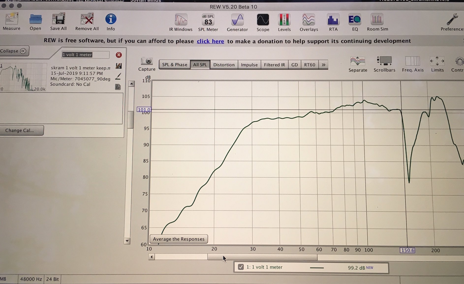
Yeah I suspect that its entirely possible that some eq tuning could change the character of the sound from the skram. The only eq applied so far is the recommended dsp settings that Danley provide for the sh46's. I didn't experiment with higher crossover points above 80 hz, its something that I want to do the next time I have them out. I will have the full system outdoors for 4-5 days aug 15 weekend so I will get lots of time to experiment some more. Here is the response of just the skram as I had it processed meeting the sh46
If one was to try applying some individual eq just to the sub to improve it, what should I strive for? More of a flat response? what about the notch's at 85 and 150 ish? Should I try to even those out?
Here is the response of both speakers together
https://imgur.com/gallery/EMtk6eN
Certainly open to suggestions if anybody has some!
The 85Hz notch is fairly narrow and shallow. it wasn't in the raw measurements so it's likely some sort of artifact or perhaps an unintended EQ band. The port resonance cancellation at 160Hz cannot be filled in. Don't worry about that. If anything you may find that adding a band of EQ to knock that peak at 200Hz down may improve it a bit. The low pass is already pushing it way down in level but it may be worth a shot to knock it back another 10+dB. You may hear a difference or you may not.
Response through the bass and mid bass region with the Danley's looks fairly smooth. For music and especially live sound or club work I'd run the bass quite a bit hotter. The crowd always loves the bass. Start with the JBL/Harmon curves and season to taste.
-
22 hours ago, medico said:
Very interested in this design, going to build one just to have a listen. and if i like what i hear i'll build 8+ of them for our rig!
one thing, our tops are bit wider than these, so would want to build them 2inch or so wider, and possibly taller, by few inches.
will this effect the sound in anyway? and how so?
also whats the best way to do so? scale everything up?
look forwards to hearing back!
Cheers,
Murdoch
Adding 2" of width shouldn't affect things much but I'd not add the height. Can you not lay the subs on their side so they are 36" wide? If you are using more than 4 or more subs you should be able to stack them or arrange side by side for plenty of width.
-
On 7/30/2019 at 3:40 PM, peniku8 said:
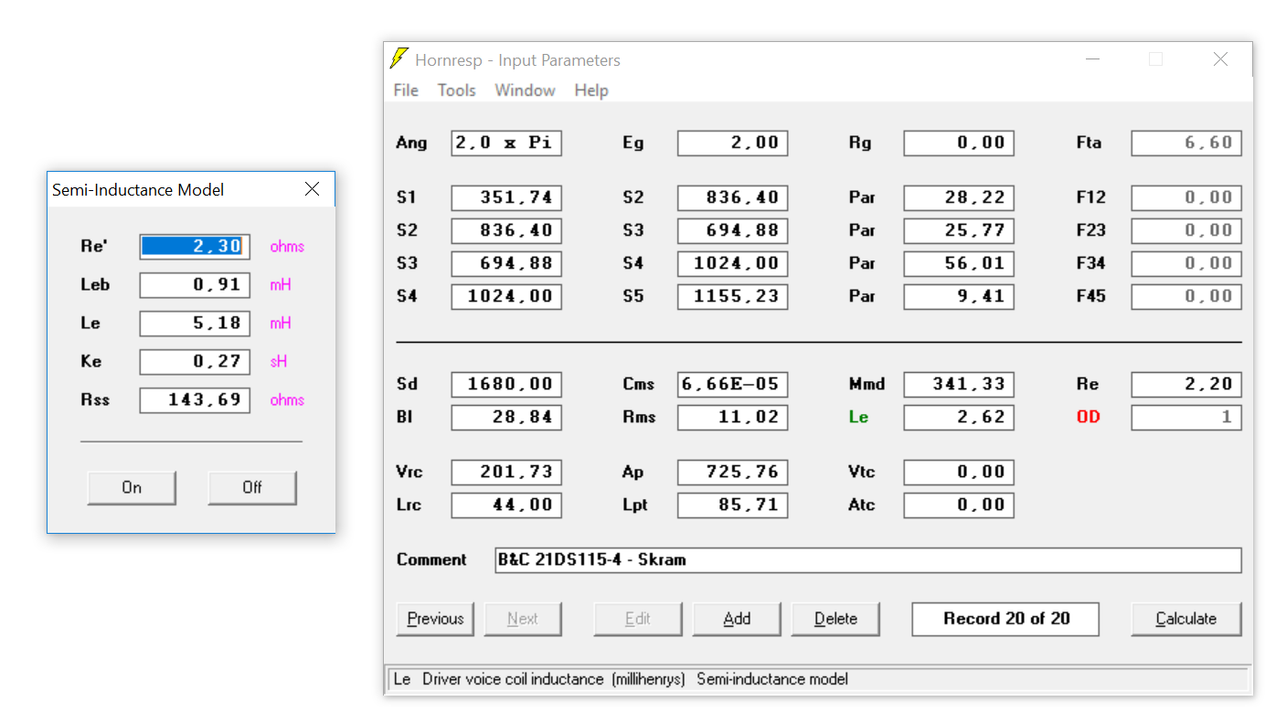
Another thing that confuses me is the fact that you did use the lossy inductance setting, but did not use the additional parameters you measured, or am I confusing things now?
When I enter values there and turn them on, the Le will light up in green. The SKHorn measurement looks closest to the simulation without these parameters (Le in red), so should I model my design (using the IPALs atm) with Le in red?
I'm trying to understand this setting, am I correct in saying that lossy inductance kinda does what the shorting ring is doing in the driver?
You should use the semi inductance parameters. Green...The Red Le setting is only a best guess for when you do not have better information to go on. I'll go back and look at my Skhorn sim when I get a chance. I've got probably 100 records or more for the Skhorn going back years so it's possible I may have grabbed the wrong one or something.
-
5 minutes ago, Timon said:
before we start building the second skram we want to make oszillating tests with test pieces. These will be like 18mm birch, 12/15mm Banova with Epoxy(and carbon), the same with poplar and birch. we are not sure zet, how the tests will look like, but we are sure to find a way
") after that we will make the second skram out of the winner design and then compare it with the orig. skram.
after that we will make the second skram out of the winner design and then compare it with the orig. skram.
Ok, those are interesting advices, so we will try it without them first. Is it a good idea to make i.e. per side one Top with both, the AMT with the Mids, and a second cab with only the Mids (eighter with the same tuning or again as a 4 way system?)
Another change in the plan is to use not the very expensive wavecore driver, but instead something like the http://www.precision-devices.com/Product-Details/PD103NR1.
Would you recommend a closed box or BR Design for a tuning around 100Hz? (And could you recommend a calculation tool for designing these?)
We want to use a FP10000Q for two skrams, another class A/B or D amp for the L/R mids and one for the L/R AMTs.
Do you prefer a single extern dsp for all amps or the build in dsp (with much more effort)?
Thanks a lot for your help, I think we are on a good way!")
If you have the built in DSP you may as well use it right? Less cables, less pieces to fail. If it does not work for some reason perhaps look into another external DSP box.
It cannot hurt to try the Skram's with the tops first. If you think you need the kick bins you can always build some later.
Let us know how the material testing with Birch, Poplar, Carbon, Banova goes. I think this will be interesting for many of us.
-
5 hours ago, Timon said:
Hey guys,
my friends and I are totally fascinated of the Skram and for now we want to build two of them.
At first we'll build it with the suggestion of 18mm birch ply and after we want to do some changes for the second pair.
We want to make it out of 15mm (birch ply and in the core of it one layer of poplar to make it lighter) in addition we would like to add some braces out of carbon and epoxy resin. It should be as stiff as 18mm birch ply.
Do you have any concerns with this plan so far?
We are planing to build one Cubo Kick 12 per Skram with the 18sound 12ND830 and a little bigger cabinet, so it gets down to about 90hz and up to 200hz.The other consideration is to build some sealed boxes as kicks but I worry if this will be very harmonic with the Skram. But it should be the purest and punshiest kick, isn't it?
There would be I guess 2 drivers per Skram (depends on the driver).What do you think? What would you do?
As Mid Tops (from 200hz with a bit different AMT) there will be one Mundorf AMT (with a horn in front of it and an active cooling system) and two Wavecore WF259PA01 per side.. Mostly we are playing Techno, etc. but the system should be able to let you enjoy all kinds of music...
I don't see any issue with modifying the plans a bit for 15mm wood. It should still be strong enough. Banova ply for the interior bracing would be nice as we were just discussing it at AVS but it seems quite expensive. Carbon and epoxy bracing sounds interesting. What's the goal though? Weight savings?
I don't generally use kick bins. I like subs that can get up fairly high in frequency and big mains that can get low with power so I don't usually add a third set of cabs. I like to put the extra weight and size of the kick bins into the subs and or mains, and have one less amplifier channel and set of DSP settings to worry about. YMMV. A lot of other guys swear by the kick bin approach. If your preference is for kick bins the Martin 215mk3 design gets a lot of praise but it's bigger and heavier than a Skram so it better be good!
It'd be hard for me to pack a pair of those when I could add another <120Hz sub cab instead unless I was already running like 8+ subs.
If I were designing a dedicated kick bin I would do a FLH, or plain old bass reflex for sure and not a TH or bandpass variant.
-
On 7/20/2019 at 5:39 PM, m_ms said:
If your use of 12-24dB BW HPF (or mostly 18dB) is implemented in the context of the subs having to endure your test-bench trials, then I take it the slopes being mentioned are sufficiently protective. I may try out 12dB BW and see whether it's advantageous in terms of sound quality, but I'm not sure it's a good idea with tapped horns if they unload more severely below tune compared to ported subs or a 6th order BP iteration like the Skrams?
As is 18dB BW HPF is preferred here over 48dB BW. The overall presentation just appears to be more cohesive.
That is correct. The relatively shallow 12 and 18dB filters have been adequate with the sine sweeps at max level which start at 2Hz. Also the pro drivers used in these and the Skhorn are VERY resistant to mechanical bottoming. A filter is recommended but there's no need for something like a 36 or 48dB octave slope for protection. I wouldn't go any steeper than 24dB.
-
1
-
-
A pair of Skram's has larger back volume and vent area over a single Skhorn. The cab is just split in half for easier moving and arranging. I'd hesitate to go much bigger / heavier than the Skhorn in a single cab.
-
Do you have the raw measurement with no filters for comparison?
-
On 7/14/2019 at 5:05 PM, peniku8 said:
@Ricci, how do you expect the new Eminence driver to perform in the SKHorn? Its stats looks pretty close to the IPAL, with the benefit of being a good fit for 2Ohm stable amps (with 3Ohm per Cab per channel), but the efficiency might be a little lower?
Since the LaVoce dropped in price here (to 350€/400$, can probably get it even cheaper) it would also be interesting how one would modify the cab to fit that driver better (slightly larger back chamber?).
NSW6021-6 looks great in either the Skhorn or Skram. No mods needed. Same for the SAN214.50. If you want a larger back chamber use the Skram.
-
On 7/17/2019 at 4:57 PM, jay michael said:
Yup! Try this

Beautiful setup.
-
9 hours ago, m_ms said:
Maybe this has been brought up at an earlier juncture, but is the driver in a Skram unloaded below tuning frequency similarly compared to a tapped horn or ported enclosure to necessitate a high-pass filter, and if so what's the proper/sufficient slope and type to use here - Butterworth, 2nd to 4th order?
7th or 8th order slope HPF are oftentimes considered too steep, but why? It should follow they offer better protection of the driver while "eating" less dB's down to the cut-off; to my ears a steeper HPF (like 8th order) makes the low-end appear slightly more extended for this reason, but perhaps also a bit too distinctive. I'm back to a 3rd order BW to see how that fares..
Yes. These unload below tuning. The only cabs that do not are those with a sealed chamber on one side of the driver, or IB.
I use 18dB BW most of the time. 12dB when I can get away with it. I never go any steeper than 24dB. It typically causes greatly increased group delay at the corner and removes any possibility of useful output below tune. Typically there is some useful output till about 1/3rd octave below tuning. Also extremely sharp cutoffs just seem to sound unnatural to me.
-
1
-
-
23 hours ago, Alexlel said:
Based on your fresh hornresp inputs and your measured B&C 21DS115-4 T&S, it looks different of your simulations in page 2, is it normal ?
Which one should we consider for now ?
It's the same for the LaVoce, higher sensitivity with those inputs.Gonna wait for some more measurements but if this one is around 98dB/99dB for 1W/1m as shown in the new simulation, I'll go for it instead of Othorn !


Use the newest one. The old ones were probably a few iterations back. I've probably got 50+ Skram records with different drivers, vent configs, front chamber configs, alternate cab designs etc. Also when siming cabs you can come up with quite different results based on where you set the section points (S3,S4,etc) and how the throat is simed. The cab hasn't changed the sim inputs have. This is why I usually try to wait until I have measurements to determine the correct HR inputs. Jay's measurements confirmed which way of siming the cab is closest. Even with a lot of previous experience there are times where it's a bit of a guess until it's measured. Like the vent behavior mentioned earlier. This is also why I never assume other peoples cabinets perform like sim'd without seeing measurements to back it up.
-
1 hour ago, jay michael said:
Working on a deal now for a pair of sm60f's. I think the 4 subs and 4 synergy horns should give me decent flexibility for both our studio space and our festival stage.
https://jaymichaelt.imgur.com/all/
Another point is everything needs to fit inside a 8 foot by 12 foot enclosed trailer, sound system, dome, scaffolding camping gear etc. We could barely make it work before, the new system is considerably smaller and approx 400 pounds lighter.
Where are you located Jay?
-
7 hours ago, SME said:
Great explanation. Thanks!
If I understand you right here, shouldn't you include this twice, at least for ground plane because the ground has the same effect as the rear wall in terms of limiting expansion at the inlet/outlet?
That's something I haven't considered much. With vents next to the ground this could account for another 2.5 to 3" (7 cm or so) of apparent vent length give or take. That's enough to drop the tune about 1Hz lower. Might be a bit of that going on in Jay's measurement too. That's something that affects any vented or horn cab that radiates next to the ground or a wall. Since these may or may not be arranged with the vents on the floor I wouldn't add it into the sim by default. The internal geometry is always in effect though.
I might have some data in the archives that would show this difference in loading the vents but I'd have to dig around. I may not.
-
7 hours ago, jay michael said:
If you take a look at my newest measurement it doesn't seem to show as low of a tune as my earlier measurements. I am still pretty new to measurements so hard to say if I am getting the best data, but I did try to follow your guy's recommendations on the second measurements
That looks close to me. 30Hz tuning is what it should be. Real world measurements usually don't show quite as sharply a defined corner, which can make it more difficult to visually pin point the tuning. Looks close to expected though.
The maximum port output is usually a little below the low frequency corner of the combined system response. This is due to the output cancellation below tuning which nullifies some of the port energy. Peak airspeed is a little below tuning usually as well. If the measurement is closer to the port than the upper frequency radiator it can show increased low frequency output and a lower corner. This was probably what was happening in the first measurements.
I've attached the sim'd response with the 21SW152-4 with semi inductance included. There are 2 traces on the graph because one shows the correct port area and apparent functional length (With the notch at 150Hz) and the other shows the actual straight vent length with adjusted vent area to maintain the correct tuning. I figured the real result would be somewhere between the two but wasn't sure which one it would be closer to. I was hoping it would be closer to the actual vent length with the smoother response above 150Hz, but it seems to be closer to the unadjusted one. It is shifted a bit better than that sim shows though. Notice that the sim rolls off much more abruptly above 120Hz towards the notch. Your measurement shows that the notch due to the pipe resonance and the upper end peaks are shifted up in frequency a little and the response is quite flat up to 150Hz before a much more abrupt notch at the pipe resonance. This is what I wasn't entirely sure about before measuring this one. Basically I was trying to trick the tuning of the ports to be a bit lower than expected so that vent area can be maximized, but also trick the pipe resonance up in frequency a little too. It worked to some extent but I was hoping it might come in a bit higher than it did. Anyway those are a few tricks I tried to use on these. It's the little things that can really be of interest sometimes.
@SME As far as calculating vent length for tuning purposes when loading into a wall it's a little bit of calculation and a little bit of art. I've been pretty close on mine so far but perhaps I'm just lucky. On the Skram the back wall actually forms a 90deg bend for the vent so I add in the chord length from the bend through the center section and then the pipe termination only terminates on one side because the other is the back panel so I add an additional half of the vent width (length from center end plane of vent to center-point of a 45deg line sketched from the end of the terminated pipe section to the back wall. It seems to be very close on this one.


-
Looks good. Took you long enough!
-
14 hours ago, jay michael said:
I did do some more frequency sweeps today, testing some new cables I made up with my k10. One thing that really surprised me is the directionality of these things. I didn’t use a db meter to measure but these things have a substaintial reduction in energy behind them, which I’m pretty excited about. My rcf’s were basically as loud behind and they were in front. Going to be handy on our festival site as we have had some noise issues in the past with a neighboring property.
Hey Jay. Thanks for posting graphs and feedback on yours.
Try to limit your graphs to 10Hz-300Hz or something like that and about a 60dB total range of SPL. Anything below about 50 or 60dB is going to be getting into noise floor anyway. You want to focus in on the data of interest on the screen.
SME mentioned measuring voltage. That's easy and useful to do. Whenever you setup to measure next time. Run a 60Hz sine wave from REW's generator through the system and measure with a DMM at the speaker terminals. If you are using speakon it's easy as pie just measure at the screws on the connector with the collar pulled back. Mark down your gain setting in REW and save it with the voltage in the measurement notes. You can calculate the voltage based on the gain as long as the gain setting is tracked.
The response shape looks good to me. Looks a little bit different above 130Hz than I expected. More rolled off above 130Hz. Do you have a low pass filter engaged? Low frequency corner seems a little lower than expected too. That could be closer proximity to the port than the horn section.
Anyway good effort. Can you tell me what frequency the notch is on the top end? 150Hz? Doesn't matter too much but it gives me some data on how the vent resonance behaves. Doesn't really matter since these are subs and look flattish to at least 130Hz or so but I was curious how it would turn out. Vents are using the back wall and have effective length much longer than the physical length. The vent resonance I was hoping would behave closer to the strict physical length than the apparent length but it doesn't seem to have worked quite as well as I'd hoped. Oh well...That's all behavior above 140Hz anyway.
I've been very busy so I haven't had too much time to check in around here lately.
-
I posted the possible vent tunings with these a few pages back. With 1 vent open it should be around 14Hz. In a room for HT, with a lot less overall headroom needed than for PA work this might be the ticket. I think 2 vents open was going to be about 19Hz.
-
Brian,
Not yet...This is the first design I ever posted prior to doing a GP workup. It'll get there eventually. I don't even have cabs yet and I think it's approaching 10 people who've already built them. Comparisons to vented have been discussed a lot. I'd suggest reading through the Skhorn thread, the M.A.U.L. thread and this one from the beginning. My reasons for using these style of cabs go a little bit beyond simple sensitivity and output gains. The short version is it buries some of the operational junk from a direct radiator in the cab and gets a few more dB before the sound audibly degrades.
-
On 6/24/2019 at 6:56 PM, SoundOfTheSaint said:
Glad we now have some more data on these, would the weaker performance at higher excursion of the 9601 make the 21sw152-4 a clear cut winner in an Othorn doing 25-80 at high power(upto 4000W~ per driver) in a PA setting? Or in real world use is there not much difference between them? Really tempted to try and sell my 21lw9601 and use 21sw152-4 instead as I can get them £100 cheaper each than the 9601, i'm really interested in how these drivers compare and any advantages of using one over the other.
I don't think the 21SW152 really offers much more excursion than the 9601. Maybe just a bit. Overall they are fairly comparable. Whichever is cheaper should work well. I don't think either would be a noticeable upgrade over the other.
-
On 6/23/2019 at 8:43 AM, radulescu_paul_mircea said:
Well, that settles it... the far grater excursion capability and lower power compression than any other pro driver except 21Ipal. The Copper coil has less thermal inertia because speciffic heat is half that of alluminum , the efficiency is a bit lower than Ipal because the magnet is not as huge, but the normal impedance is high enough to use 2 of them easily in parallel on a K20 channel or even X4L with extreme results.
This RCF LF21N551 need to be tested by you @Ricci. It will really surprise you!
I may see about getting the RCF for a next round of 21's, but it will be quite some time. Still no availability of 21TNLW5000 over here.
Yes this and the 21IPAL are definitely a cut above any of the other pro 21's I'm aware of. I may try to power a single 21Ipal in the same box with the SP1-6000 for a more direct comparison, but I'm not sure how well even that amp will deal with impedance mins <1ohm during the sine wave sweeps. The K20 did not like bursting into it way back when I tried it. The impedance on the Eminence is a big selling point for me. MUCH easier to power in singles or in pairs. The NSW6021-6 gives up a little bit of motor force to the Ipal but I think I like the mirrored spiders and spacer setup for the suspension better.
Hopefully these put other mfg's on notice and inspire more competition.
-
 1
1
-
-
A K10 should be a great match. Any of the big touring amps would be capable.
Other options would be Crown Itech-12000 / Itech 4x3500HD / MA-12000, QSC PL380, Speakerpower SP2-8000 / SP2-12000, etc...


Ricci's Skram Subwoofer & Files
in Bass Projects
Posted
In case there was any doubt yes a lowly Behringer NX amp is capable of smoking a 21DS115 or most any other driver with the right/wrong? circumstances.