SME
-
Posts
1,702 -
Joined
-
Days Won
111
Content Type
Profiles
Forums
Blogs
Gallery
Downloads
Articles
Media Demo
Events
Everything posted by SME
-
Just a quick update. I got my amp back and will hopefully get a fully working replacement Motu A16. Without that, my system is basically dead because I don't want to mess with the mess of cables that hold together my current "signal chain from hell". I did some thought experiments for surround designs. I looked at a few options involving coaxials, but I'm not sold on them. No one is showing measurements of what happens when the woofer is moving a few mm back and forth. As far as those designs go, I think the Eminence CX-10 looks decent, and the wife would certainly appreciate seeing less speaker. However, given my room layout, I think my best option is to use a SEOS-15 horn turned on its side and matched with a pair of 6.5" woofers such as the AE TD6H, oriented vertically and to one side of the horn. I'll have to double check, but I believe I have enough gain from corner loading to get 80 Hz extension from a sealed box with a much higher resonance. The AE TD6H in particular look like that can deliver a nice low Q roll-off in a very small box. The sensitivity of 97 dB/2.83V (4 ohm speaker) is only a little less than my fronts, and the bass gain would in principle make up for the reduced displacement. I'd love to go with 8", but I think they will be too big and won't integrate as well with even an SEOS-15. Edit: And I forgot to add that after looking over my data more carefully, I believe that my woofer enclosures are tuned closer to 45 Hz with the stuffing added. Both impedance and inside port measurements point to a tune of 45 Hz with the phase zero-crossing hitting 45 Hz on the mark. I'm a bit surprised my design ended up tuned so low with such a short fat pipe, but I suspect that the tight dimensions inside the box may be contributing to a longer effective port length. In any case, I'm still quite happy with the responses. Once I get them up and running, I can push them a bit more to see if any issues arise. Oh, and as a point of minor fascination to me, I've never seen anyone post measurements of inside their ports. I was surprised at how easy it was to clip the mic at 120 or so dB with it stuck in the port. So of course, I had to put my fist in it and enjoy a free "wrist" massage.
-
I'm glad you took it slow. That may be the only reason your scope didn't go up in smoke. I'm kind of surprised that those grounds are electrically connected. I would think that would cause problems in a variety of scenarios in which you'd want to use both sets of terminals at the same time. Out of curiosity, have you measured the pair of ground terminals with the DMM in resistance mode? If the resistance is not very high, that would confirm there is an issue there. If it is high, I might try running a low current impedance sweep on it to see if the two are isolated only at DC. It's a bummer that the scope doesn't work here, and I agree that the history data would be very useful. I'm thinking that most amps will sustain a high output for a relative short period of time before clipping sets in. With the history recording, you could see how long it takes for that to happen.
-
So I did get the listen to the horns on Sunday as well as listen to the woofers in stereo. I listened to the horns mostly in mono (one at a time) with 40 uF capacitance in series and the channel crossed over to the subs at 250 Hz, the max supported by the AVR. Having some bass definitely improved the experience. In fact, I thought they sounded fantastic despite the hole in the mid-range response. There was enough mid-range, for the most part, to hear what was going on, and the 1 kHz+ sound was very smooth. I had to pull myself away from just listening in order to take a few measurements before I ran out of time for the night. I'm not posting the data because I'm not too happy with it. I will need to plan better to get some better measurements. At the same time, my preliminary sensitivity measurements suggest my measurement gear may be reading at least 2 dB, perhaps even 3 or 4 dB too low. I guess that's not unreasonable given that my reference is a Rat Shack meter. Perhaps it's time to splurge and get a calibrated SPL meter or get a new mic with calibrated sensitivity, in addition to calibrated frequency/phase response curves. I was planning to move forward with adding resistance in series until I did a bit more careful study of the problem and realized that series resistance alone is probably not the answer. The background hiss from the horns was very audible due to noise in my signal chain and their very high sensitivity. In fact, my wife complained it made her feel uncomfortable and that it remained audible at moderate listening levels. My best guess is that the MiniDSP OpenDRC-AN units are the culprit. I noticed a significant bump in background hiss from my current speakers (enough to *just* hear at the listening area) when I added those units to my signal chain. I was disappointed because I had been getting by fine with only RCA, but the balanced connection between it and the amp didn't seemed to help at all. I think those units may be somehow flawed in their design. Once I have custom DSP with my Motu A16, I'll be very glad to part with those things. On Monday, I finally got the RMA finalized and shipped my Motu A16 back. It looks like I can anticipate at least a two week wait due to shipping alone. In the meantime, I have a fair bit of code to write so that I'm ready to rock when that unit comes back. My freshly re-soldered Emotiva XPA-5 amp is arriving tomorrow. I've gotta say, I thought the hard part about this whole DIY thing was going to be in the shop, but instead, it's the incredible pain involved in finding and acquiring the parts that are needed for the task. I believe this project has so far led to a total of product re-orders and/or RMAs due to errors or quality issues. I have a new respect for those who go through the trouble of manufacturing things to sell and persevere despite the constant hassles of having to deal with vendors. The more infuriating issues were with totally trivial things that were too cheap to bother returning. Amazon.com sent me a router bit package without the router bit, but I had to wait 13 days to receive the shipment before I realized I would have to re-order it. I'm done ranting. I have a couple weeks to get as much done as possible with my DSP code so that I can dial-in a useable crossover and integrate the new speakers into my system. I'll also dive into more measurements so I can work on optimizing their responses. Then I will experiment with different combinations of baffles and/or absorbers to try to clean up the low-end response and directivity. I am tentatively planning on placing them toed-in at 45 degrees as close to the front wall as possible. With the woofer centers located about 14 inches from the rear wall, I'm anticipating a fair bit of 250 Hz suck-out, which I expect I can partly mitigate using some appropriately placed OC703. On the other hand, if I can use a reflective baffle surface to smooth the transition between the face of the speaker and the wall, then I can maybe get a flatter response without having to give up as much efficiency. Note that the absorber essentially dissipates much of the rearward wave coming from the speaker, and that's a lot of energy to lose. I know that a very large continuous baffle is ideal, but I want to see what kind of compromises are possible as well as seeing whether I can use baffle design to help increase forward axis directivity at frequencies further below the crossover.
-
I'm definitely curious to hear how this is resolved. I definitely would be wary of connecting anything that could create a voltage difference between those two grounds, given what you've observed. I'm actually surprised that a fuse didn't blow or something.
-
I just finished sanding the last box. Tomorrow I'll hopefully finish the other woofer. Then Sunday, I can work on getting the horns ready for preliminary testing, if I don't lose too much of the day to listening to the woofers in stereo. If there's time, I'll make changes to the protection circuit as needed. I doubt I'll find the horns as nice to listen alone as compared to the woofers. Then I just have a lot of work to do with code while I wait for my electronics to be fixed. The waiting is going to make me crazy.
-
It'll probably be at least two weeks before I do any polars. I expect I'll need to block at least one weekend day for the effort including time for setup. I also have to figure out exactly how I'm going to set up the measurements. It'll probably just be in my living room at about one meter distance and a short impulse response window. That's not really ideal, but it's way less hassle than trying to rig something up outside. I may be able to use some spare acoustic foam to my advantage too. We'll see. This weekend, I hope to finish the woodwork on the other cabinets and get them wired up with capacitors for protection during preliminary testing. Then I can see what kind of sensitivity I get across all frequencies and decide how much resistance I want to add. After that, I have no idea. One of my XPA-5 amps is with Emotiva to fix a bad XLR input. Worse still, it appears that all the odd numbered (top row) outputs on my Motu A16 have electrical issues, and I am still working through tech support who will likely have me send the unit in for service for what may be a crappy soldering job or maybe even just a loose cable. I do still have a fair bit of work to do still on the DSP software, but I'm almost to the point where it would be frustrating to not have the A16 around for testing. Worst case, I'll find other stuff to hack on. It's just going to drive me crazy to have two finished speakers but no crossover. They are really too big to be permanently placed in my room anywhere except where the old front left and right speakers reside. I'm even half tempted to try to work out an interim passive crossover but I want to see where the thing with Motu goes.
-
TD12M woofer and in-box measurements are posted here. TD12M Woofer Impedance Caveats: This woofer was not yet broken in. The measurement taken with the woofer firing up instead of forward, which is known to some error. TD12M Woofer In-Box Impedance This is in a ported box of about 1.5 cubic feet internal volume. TD12M Woofer In-Box Response (close mic) I aimed for a tuning frequency somewhere in the 40-70 Hz range. I was pleasantly surprised to see the tune came in right around 45 Hz with the port tube at its minimum length with a response that has a very nice over-damped roll-off. I'm glad I opted to make the bass box a bit smaller than I originally planned! In fact, I'm very pleased with the end result: Note, these are un-smoothed close-mic measurements, so these shouldn't be interpret as absolute but merely illustrative. The one on the bottom is before I added acoustic foam to the box. That 240 Hz resonance was particularly nasty and contributed an impedance spike as well (not shown). The foam totally nuked it. I installed a pretty generous amount of foam (more than would be typically recommended) into a box that was already somewhat cramped. The port exit is not really one port-diameter away from some of the internal surfaces, including the rear, but I did my best to give it as much clearance as possible. Nevertheless, I really wanted to kill those resonances and wanted to stop as much mid-range sound from coming out of the port as possible. Thankfully, I don't see much evidence of output loss due to the heavy stuffing. Here's a comparison of ported versus sealed close-mic responses after stuffing: These were done even further off-axis from the woofer and were closer to the port. The ported box gains 2-3 dB over something like two octaves, and I believe that excursion should be better controlled in the ported version in the 40-80 Hz range. The port does cause a bit of cancellation in the mid-range, but the losses are under 1 dB for the most part and diminish before the port resonance a tad above 1 kHz. I've also confirmed sufficient attenuation of sound in the port using inside port measurements. It's possible that the tuning frequency was lower than expected because the lack of space around the port inside the box effectively increased the port length. Unfortunately, this probably also increases turbulence and may cause problems with chuffing and/or compression at high levels. I may need to do some compression sweeps to verify that these things can breathe at higher levels of output. The results may impact how low I choose to cross them over in the long term. Horizontal Polar Response (in-box) Here is a normalized 2D colormap plot of the horizontal polar response windowed to 4 ms and normalized to 30 degrees, generated with tools provided by 3ll3d00d: These measurements were done indoors but were only slightly contaminated by reflections within the window period. Edit: Note that the data is clipped at "+3 dB". A better picture of the polar response pattern emerges if we normalize at 0 degrees: That looks much better. Whatever cone break-up exists in the TD12M doesn't seem to perturb the polar response much at all. Nothing like the break-up in the DNA-360. Vertical Polar Response Here is a normalized 2D colormap plot of the vertical polar response windowed to 4 ms normalized to 0 degrees: Edit: I updated this image to better use the available color range. These measurements exhibit more contamination from reflections than the horizontal polars. This effects the measurements taken far off-axis in particular because I could not properly absorb the ceiling reflection.


-
Horn / CD measurements are posted here. DNA-360 + SEOS-15 Impedance This measurement is without capacitors inline. All others that follow use capacitance in series for protection. There is diaphragm break-up at 17 kHz, and this feature appears in the other measurements. DNA-360 + SEOS-15 Passive Circuit Even though this system is a fully active design, the compression drivers use passive circuits to flatten the response and cut back the sensitivity a lot to reduce background hiss. They look like this: Here is the response before and after the crossover: Horizontal Polar Response Below are horizontal polar response plots in 7.5 degree increments (un-smoothed with 3 ms window) of the DNA-360 CD inside the SEOS-15 horn, taken at 0 degrees elevation and 1 meter. SPL figures are only correct in a relative sense. (Note: This plot has been corrected, but note that I messed up the measurement at 75 degrees, so that trace is missing. Looking at the data, I don't think that leaves a big gap.) I was surprised to see that the horizontal pattern is a bit wider than I expected from looking at others' measurements. To my eyes, this is a 120 degree horn rather than a 90 degree horn. An interesting feature here is that the pattern is actually tightest in the 2-3 kHz range and is also a bit tighter in the 3-5 kHz range. Otherwise, the response is very smooth, beginning to drop off at between 30 and 37.5 degrees. Note also the big peak at 17 kHz, which is due to diaphragm break-up and is also visible in the impedance response. Here is a normalized 2D colormap plot of the horizontal polar response, generated with tools provided by 3ll3d00d: I chose a normalization angle of 30.0 degrees. This involves a toe-in of about 52.5 degrees in my room, but because the seating is spread out so widely, I'm leaning toward this configuration to get the best seat-to-seat coverage. Note that the 17 kHz break-up is largely gone at 30.0 degrees, which is why the middle is very dark there. (Edit: The dark area is actually clipped with respect to the color scheme. See the plotted polar responses. The 17 kHz response is actually over 10 dB higher at 0 degrees vs. 30 degrees.) In practice, I would probably EQ most of that break-up peak out to keep the speakers from "glaring" at people sitting on axis of them. Otherwise, the ripples in the middle aren't as bad as they look. The normalization makes the response ruler flat at the normalization angle. A much better approach in practice is to consider frequency response at multiple angles so that EQ effort is put into correcting defects that are consistent from seat-to-seat to reduce these ripples. Vertical Polar Response Below are vertical polar response plots (un-smoothed with 3 ms window) of the DNA-360 CD inside the SEOS-15 horn, taken at 0 degree azimuth and 1 meter. SPL figures are only correct in a relative sense. Note: The increments vary here because I wanted more data for the region that people are actually likely to be listening. From 0-30 degrees, the increments are 5 degrees. Beyond there, I measured at 45, 60, and 90 degrees. Looking closely, we can see a portion from 15-17 kHz where the SPL at +/-10 degrees or so is higher (a lot higher, actually) than it is on-axis. Similar features are visible in other measurements I've seen. These are also visible in the vertical polar, this time normalized to 0 degrees: It's interesting that the vertical pattern stops expanding at around 1500 Hz and remains consistent for about another octave. I imagine again that this is a feature of the box as much as the horn on its own. These measurements were done with an extended baffle above and below the horn. (Update: measuring the horn with baffle extension below but not above the horn causes the vertical polar response to widen a lot less from 2.5 kHz to 1.5 kHz and to widen more gradually in general down to 500 Hz where it again matches the polar response in the measurements shown here.) The features starting around 13 kHz are also interesting. There is a null in the response from 13-20 kHz, except in the vicinity of the break-up at 17 kHz, which beams heavily on-axis. There is plenty of good cause to roll-off the response pretty aggressively from 15 kHz on up, and this more or less defines the maximum frequency at which the horn + CD combo behave as desired. Above there, EQing flat on-axis will lead to an over-abundance of room energy at those frequencies, which can make the sound seem glaring and bright throughout the room. Perhaps not coincidentally, 15 kHz is also where I start rolling off in my current EQ setup. (This was chosen by ear rather than by looking at measurements. No big surprise here. Power response matters a lot for these high frequencies, in my experience.) DNA-360 Linearity of Response vs. output Here are sweeps to show the response linearity the DNA-360 CD in the SEOS-15 horn. The plot consists of multiple sweeps at successively higher levels. Each sweep is labelled with its norminal level (e.g. -20 dBFS). I did these sweeps with my current crossover and EQ filters so I could assess its performance relative to WCS of actual content play at reference level. Note that my current calibration has the high frequencies collectively attenuated by -5 dB from the "85 dBC theatrical standard". So, "-20 dBFS" is actually approximately 80 dB in the listening area. (The SPL scale shown in the plot is not correct in an absolute sense.) These sweeps are windows at 10 ms and smoothed to 1/48th octave Break up's are a bitch. Having discovered non-linearity of the break-up in the cheap Ti CD in one my Hsu speakers, part of what I wanted to see in this test is how the break-up at 17 kHz would behave has SPL got pushed higher. Here we see that this nasty break-up exhibits non-linearity, starting with the -8 dBFS sweep. At first glance, it appears that the output begins to compress, starting with that sweep. However, what actually happens is more complicated (and far nastier!) than that. Note that the sweeps at and above 8 dBFS actually show ripples that weren't there in the earlier sweeps. Time-frequency spectrograms (5 ms window) for -14 dBFS vs. -8 dBFS reveal just how nasty this transition is: Note all the ringing that shows up for the -8 dBFS sweeps. This ringing actually increases the audibility of the problem even though the SPL appears to drop, and each louder sweep increased the ringing visible in the spectrogram substantially. As a point of note, I wore over-ear hearing protection for the sweeps at -14 dBFS and above. However, in the -8 dBFS and higher sweeps, I could clearly hear the driver producing lower frequencies (!) when it hit that break-up region. The sound had a weird kind of "boing" sound to it. Because this break-up is non-linear, it will resist treatment with EQ. There is at least a chance that, using some EQ to knock down the break-up in the first place will stabilize the driver for those frequencies and allow it to play a lot louder without behaving erratically. I will have to try it and remeasure. OTOH, I'm thinking this kind of thing is common to almost all high frequency drivers and may substantially account for perceived differences in sound when things are otherwise EQed to the same response. Some drivers (made of Be?) may only exhibit this kind of break-up above 20 kHz. Larger drivers may exhibit problems at significantly lower frequencies. Something that's unclear to me is how the break-up will respond to actual content vs. sine sweeps. I can play sine waves cleanly to 86 dB at the MLP. I surely ought to be able to play transients cleanly to that level as well. Somewhere between 86 dB and 92 dB, sine waves at 17 kHz will make the driver badly distort. But does that mean that transients at 92 dB will distort badly? (This is a totally reasonable SPL for a HF transient.) I have no idea. At the same time, I wouldn't be surprised if this driver is actually better behaved, on average, than other drivers on the market. Being that I'm not aware of any other measurements like I've done here, it's hard to say for certain. In any case, this issue at 17 kHz is definitely the "weak point" of this driver. It's the problem that's most likely to make it sound other than reference, and the SPL at which this may happen is way below the max SPL that the driver is capable of. DNA-360 Distortion with "High Level" Output Here is a plot of the distortion harmonics and THD versus frequency for a "-2 dBFS sweep" performed in the same manner as the linearity tests above but as part of a separate measurement. In other words, this is playing at about 98 dB at the MLP, about 10 feet away from the horns. This measurement was done with a different set of filters engaged than for the linearity tests because they were done later and reflect updates to my DSP settings. There is a high pass filter at 950 Hz and 40 uF capacitance in series for another 6 dB/octave starting at around 500 Hz. THD is dominated by 2nd order distortion throughout the pass-band. The peak THD in the pass-band is around 4% at around 1.5 kHz. THD remains below that figure all the way down to 600 Hz. This driver appears to handle the low crossover point and gentle slope very well, and this is despite the fact that the driver response falls off quite slowly in the 700-1000 Hz range.


-
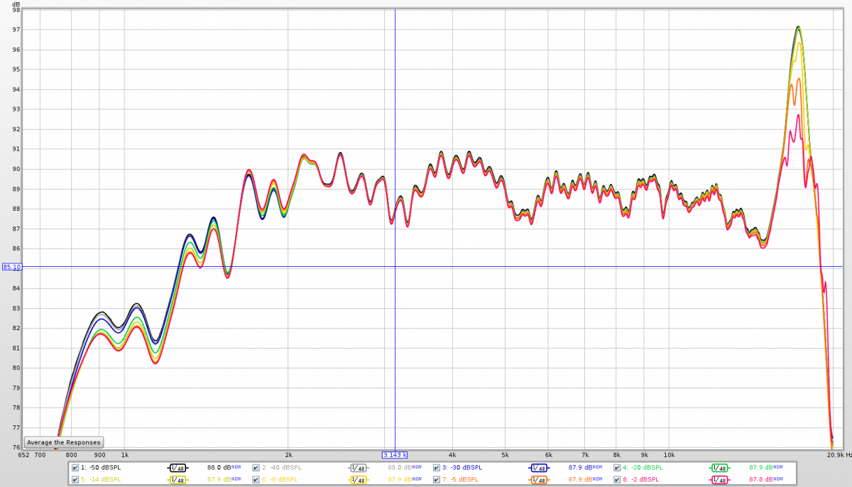
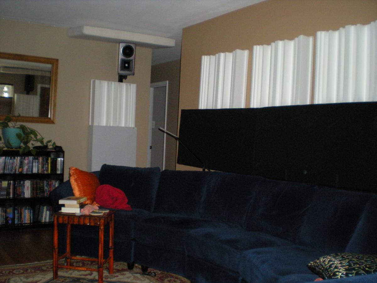
The Room Here is a picture of the front stage in my living room as of August 2016: And here it is with the TV moved off the wall and the new center channel installed: Here are some pictures of the rear of the room as of September 2016: Regrettably, I did not take a picture of the front before I replaced my old cabinet with the racks or the front left/right speakers Hsus with my SEOS-15 TD12M prototypes. In case anyone is wondering, yes, this space is very acoustically challenging, but it has its upsides. Speaker / Room Calibration Through the years I have experimented with a variety of methods of speaker and room EQ. In my current approach, I mostly ignore the room, except for the subs, and I attempt to primarily correct the first arrival of sound. I aim to make the first arrival *mostly* flat. To analyze only the first arrival, I use the frequency dependent window feature REW with a crude 1/3rd octave resolution. This is roughly consistent with the bandwidths of the ear/brains filters. It's long enough to allow for delays at the crossovers but not so long as to allow inclusion of room reflections that the ear/brain could theoretically isolate. Note that this particular FDW length may not work well with other speakers or other rooms. YMMV. I say I aim for "mostly flat" because I use a bit of sub bass boost (boost of the bass in the first arrival, actually) and because I use configurable high frequency adjustments to optimize playback for different content. Because the HF adjustments are configurable, I leave them disabled (flat in the treble) in the measurements below, but these measurements *do* include the sub bass boost. A flat-ish first arrival in a listening room that's not acoustically dead tends to result in a frequency response that is sloped up toward the bottom end. Below is my frequency response for left, right, and center with 1/3rd octave-smoothing: Note that the responses look rather messy and exhibit about 8 dB difference between bass and treble. Note that with high frequency adjustments, the difference tends to come in closer to -10 dB @ 10 kHz vs. 20 Hz. Note also that the center channel response appears very hot in the mid/upper bass. This is because because of speaker/room interface issues that I currently have. The speaker is very close to the bare wall behind it, and this causes most of the sound of those frequencies to disperse diagonally and to the sides instead of forward. As such, the first arrival is relative lean. Now look at the first arrival responses, using FDW in REW with 1/3rd octave resolution: These responses appear rolled-off at the ends because these frequencies are somewhat delayed (ends of the bandwidth) and escape the influence of the filter. Apart from this, they are very smooth and flat, except for the aforementioned sub bass bump. The center is a bit messier in the mid/upper bass again. I could have made it ruler flat at the MLP here, but I opt instead to compromise a bit for off-center seats. Indeed, think this may sound more balanced, to the extent that the brain uses information from early reflections to ascertain the content of these lower frequencies. I'm not exactly sure at this point. The configurable high frequency adjustments are of three different kinds: distance compensation, upper mid-range tilt, and X curve. The measurements below depict the effects on the high frequency response of my center channel from using -0.75 dB of upper-mid tilt (blue line) and several degrees of distance compensation (red lines) on the high frequency response of my center channel: Distance compensation mostly affects frequencies above 8 kHz or so. Almost all recordings need this compensation, in part because high frequency sound naturally rolls off with distance. I chose to model this roll-off on actual physical data of distance roll-off, and it seems to be working out quite well. There is no standardized distance for monitoring music or theatrical recordings, and furthermore, a lot of music is monitored on near-field monitors that implement some kind of roll-off of their own. The consequence is that the optimal roll-off varies substantially by content. For mid range tilt, I currently use a Q 0.5 @ 2 kHz high shelf filter with variable gain. I'm not sure this is really optimal, but it works pretty well for me. Most stuff sounds good either flat or with a tiny bit of treble reduction. Rarely do I need more than -1 dB. I'm not sure why this is necessary other than perhaps precedence. Monitors in days past likely had just a bit of tilt, and the precedent stuck. A lot of monitors include a HF trim switch that engages a tilt like this. Of course, every design is slightly different, and many include additional > 8 kHz roll-off here as well. Lastly, I have X curve correction, which is used only rarely for movies that need it. Movies mixed on a dub-stage tend to use speakers behind an acoustically transparent screen, and this almost always introduces high frequency roll-off of some kind. Instead of compensating by making adjustments to the monitoring system, tended to boost treble in the mix to compensate. The X curve was intended to standardize the high frequency roll-off in the playback system so that mixes would translate, and it was based on the roll-off that was commonly observed at the time. (IMO, it largely failed because it measured pink noise energy response instead of first arrival SPL.) AIUI, dub stages largely ignore the X curve these days opting instead to simply accept the faults of the screen but also avoid hyping the high frequencies too much with the understanding that doing so may make the mix way too bright in some settings. In any case many movies, particularly stuff from the 90s and older, do benefit from some additional high frequency reduction, and the X curve shape is probably the most generically useful. The Speakers Click this image. It is an animation of the box assembly sequence: The cabinets are separate, and I'm building a left and right pair. The other bass box is visible in the background, surrounded by a bunch of clamps. On the bottom is an AE TD12M-4A in a 1.5ish cuft box with an aggressively flared 4 inch port. The cabinet is 1/2" B/BB plywood with double thick front baffle and pairs of shelf style braces running horizontally and vertically (4 braces total). The design is somewhat noteworthy for being under 9" deep. On the top is an SEOS-15 horn with a Denovo DNA-360 mounted on it. The horn cabinet is 1/2" B/BB and is not braced. It is slightly wider and deeper than the bass cabinet, partly because I started them before I started the bass cabinets and changed my mind and opted to make the bass cabinets smaller. These are currently up and running with fully active crossovers and EQ provided by a prototype version of my custom DSP software, running on a Linux PC with a Motu A16 interface connected via USB. Each mains driver is powered by a channel from an Emotiva XPA-5. The amp is rated for 200W/300W into 8/4 ohm with all channels driven, but I expect to "effectively" get 500-700W peaks for the 60-120 Hz range due to the resonance above the tuning frequency, the very low DC resistance of 3.2 ohm, and the amp's beefy power supply that'll be hardly tapped to run the horns. So far, I am very pleased with the performance of these speakers and active crossover. Here is the a recent measurement of the response (no gate, 1/6th octave smoothing) of each driver playing separately and in unison along with the subs. (Note that I'm tweaking the response all the time. I'll try to keep this image current, but it probably won't work out that way.) This measurement was taken with a -30 dBFS RMS sine sweep and a calibrated mic. The pink noise calibration signal (-30 dBFS RMS pink noise band-limited to 500-2000 Hz) reads at about 73.75 dB. I zoomed in on the data a lot, which makes the response look ugly, but in reality I'm +/-4 dB or so with 1/6th octave smoothing everywhere except for the big dip at 165 Hz. Even though my room has some treatments, I still have some significant acoustical problems involving the floor and ceiling, which accounts for the unevenness. I could have EQed much of that out, but for the time being, I'm concentrating on EQing the speaker response and avoiding acoustics, and I have purposely slanted the response through the mid-range to obtain a flatter power response. The crossover filters, 2nd order HPF for the horns and 4th order LPF for the woofers, are centered at 950 Hz. Note that the woofer and horn aren't completely in-phase here. This is an experiment, in which I have purposely mis-aligned the drivers in time to try to steer the lobe above or below the MLP, putting the MLP closer to the edge of the lobe. Then, the response must be boosted to avoid a dip, and this increases power response too. That's a good thing because directivity typically goes through a maximum where two drivers are crossing over. The idea here is to avoid that directivity peak to achieve both smooth direct response and smooth power response through the crossover region. My measurements suggests that the strategy works, but it's not clear how this affects the sound at off-axis locations that may be at a slightly different vertical angle. The cross to the subs is at 110 Hz for now because that works best with the filters on the subs as they are now. In the long run, they will be blended with the subs over a wide frequency range to optimize multi-seat response. This means, I am also planning to build subs that can player higher than the traditional 80-100 Hz as well. This is the first part of a larger project to upgrade all the speakers and DSP in my system to fully DIY-built solutions. I have started building a center channel of identical design, and I have drivers for new subs and surrounds drivers on order as well. Edit: Added details about speaker/room EQ configuration and in-room response.


-
Okay. I wasn't sure what the actual dcr of your setup looks like. You look to be fine for 1.5 ohm. FWIW, the magnitude of the impedance never drops below the DCR. I gather you are running two drivers on each amp channel then with a series-parallel or parallel-series configuration between each pair of drivers and each pair of voice coils on each driver? Good luck on this. It should be interesting to see what you find out.
-

The Low Frequency Content Thread (films, games, music, etc)
SME replied to maxmercy's topic in Bass Content
I'll comment on this one when I get around to seeing it, but I thought the first "Despicable Me" had a better soundtrack with better bass than its sequel. I also liked the first film more than the second. -
FWIW, I estimate that the 0.01 ohm resistor will still see 60 W, not 40 W with the amp pushing 6 kW. At least that's in the ball park, but I'd probably opt for more power handling. As lilmike suggested, you can always combine resistors to spread out the heat. Four resistors in a series-parallel or parallel-series configuration will get you the same resistance but 4X the power handling. Sorry in advance if you don't like the math. For the amp, P_amp = I^2 * (R_load + R) with P_amp being power in watts, I the current in amps, R_load being the resistance (DC impedance) of the driver in ohms, and R is your resistor value in ohms. Your resistor will have to dissipate P = I^2 * R power. These equations combine to yield: P = P_amp*R/(R_load + R) = (6000 W) * (0.01 ohm) / ( 1 ohm + 0.01 ohm) = 59.4 W With R being so small we could "assume" it is zero (negligible), giving a very close (1% error) estimate: P = P_amp*R/R_load = 60 W Or for any particular *small* value of R: P = (6000 W/ohm) * R Note that because you are trying to measure the amp power output rather than the power input to the driver (right?), you will probably want to put the volt meter across the amp terminals instead of the speaker terminals. Otherwise, your math must consider the effect of R on the total power delivered by the amp. In fact, your error will be equal to the amount of power dissipated in your resistor. For your 0.01 ohm resistor, this will be 59 W, or about 1%. This is of borderline importance if you are using a resistor with 1% tolerance (i.e., about the same amount of error), but at least you can avoid this error.
-
This setup looks good. I think you want a resistor rated for more than 50W or a lower resistance. Didn't you say you had a load that dropped down to nearly 1 ohm? Supposing your amp is pushing 80 V rms to achieve 6.4kW into 1 ohm, your 0.1 ohm resistor will see about 8V and will be dissipating something like 640 W. Yikes! I don't think you have to worry about inductance in the resistor for testing subs unless it's unusually high, like 1 mH or more. Edit: I'm fairly certain the power dissipation problem is the reason the maximum current measurement in the Fluke and other meters is limited.
-
Nice find! It's a bit pricey, but I think that might be nice to use for power handling studies too. My thinking is that impedance increases should correlate quite well with voice coil heating. This can be used to measure temperature versus time for different amounts of power input (and possibly different frequencies/excursion) to understand how well the woofer dissipates heat, both in the short and long term.
-
I completely concur. Tactile sensation of sound is very complicated. Whereas we only hear with one pair of ears, a multitude of different sensory organs contribute to the vibrotactile sense. Then there's the multitude of ways that the energy can reach those senses. While talking about the tactile, we also have to talk about sound above the subwoofer region, which can contribute quite a bit of sensation in the chest. I know I've felt tones upwards of 200 Hz in my chest, and I'm willing to bet that many of the ladies feel sound quite a bit higher due to their smaller diaphragms on average. I'm still pretty skeptical about the sound intensity playing a role. When we talk about FR, we rarely specify what kind of smoothing is being used in the comparisons. So-called "transient response" may have a lot to do with it, in addition to vibrotactile considerations, and transient response may be made to disappear from the FR if too much smoothing is used. I believe 1/24th octave is the absolute minimum for bass. For < 120 Hz, I usually prefer to review my measurements responses un-smoothed and a very long time window.
-
You look like a great candidate for independent DSP on each sub. Your room and sub placements are very asymmetric (as far as bass is concerned). Do you at least use independent delays on those guys? Delay optimization alone could improve your 60-100 Hz response quite a bit.
-
I mostly agree with Dave here. While higher motor strength and higher Qts is a big benefit, all else the same, for the cost it just doesn't make sense to me. Only if I was highly constrained by both size and available power would I look its direction. Most likely, adding an additional amp and additional cheaper drivers (with smaller mounting depth so I can fit them all in the box) to distribute the power across would be a much more productive use of my money and would have the added benefit of demanding less excursion (less suspension related distortion) for the same output.
-
The Low Frequency Content Thread (films, games, music, etc)
SME replied to maxmercy's topic in Bass Content
Wow. It looks like this shaping up to be a good year as far as ULF is concerned. I'm so behind on movies lately. I've been working hard on my DSP software, designing my new front speakers, and moving to new equipment racks. Once the mains are built and my front stage rearrangement is done, I'll work on sub upgrades. -
I'll post this link from the Speaker Power web site again. While we can't really consider this to be an unbiased source, it's interesting that a similar performance pattern is shown for the Lab Gruppen FP14000. Long term power output (before thermal) is shown to be limited to 1500W no matter the impedance. All lower impedance does is reduces the time it takes for output to be limited. From what Luke has described, I'm almost certain some kind of protection or limiting system is activating. If anything other than his amp were clipping, it would almost certainly be present as soon as the signal was played and not after some length of time. The fact that the amp is limited to a fixed wattage further supports this because if the voltage were clipping anywhere in the circuit, the max power output would still change with differing impedance. Could it be clipping inside the amp? I don't think so. Not with the "pulsing" that Luke describes. That sounds more like the work of a soft limiter. I don't see anything in the pictures that suggest any kind of user-selectable limiter is enabled. In the other amp thread, there was some discussion about "protection circuits" and what constitutes good "protection circuits". In the case of modern amps, I believe the firmware logic is more important than the parts used. I am not an EE, but I do know a lot about software and have studied a fair bit of control systems theory. Leaving aside the more technical issues, one must make decisions that balance performance, safety, and reliability among other things. What both Luke's and SpeakerPower's (not sure whose name to credit here) results suggest that the protection circuitry in the Lab Gruppen amps is very conservative. We are left to wonder why this is so. Perhaps it ensures that it won't overheat, even if it's being used in full sun in the Persian Gulf, or maybe it's supposed to protect connected drivers from damage in the event of abuse or unexpected faults. Maybe I'm just giving too much benefit of the doubt to the product.
-
Nope. What makes you think it's bus pumping? It sounds to me like you are either draining the capacitor reserves, which would cause clipping, or you are observing a limiting/protection circuit, which could either clip or soft limit. That you heard frequency doubling suggests a lot of 2nd HD, which *might* be consistent with soft limiting. I'm betting the clip lights only light when some voltage (near the max) is exceeded. By the way, I expect almost all of these amps will behave this way in the sense that the max power output will drop a fairly short time frame with a continuous signal. There's a max voltage that an amp can output into any load. (Bridging doubles this figure.) If you exceed that, you clip. If you start pulling peak levels of power from the amp, the capacitor reservoir will be drained as the power supply can't keep them charged at full voltage. This may cause the max voltage (and clip point) to droop over time. At some point, the reserve will be drained, and the max voltage will be limited by the capabilities of the power supply. As more time passes, one of several protection circuits may kick in. For example, parts of the amp may get too hot or too much current is being drawn from the main supply. Such an amp can pull much more current from the mains outlet than the outlet is rated for, but only for a short period of time (a few seconds). After this burst period, the amp must limit current to 80% of the rated load to avoid tripping the breaker. That LP is limiting at a measly 500W? That's way less than a 120V/15A breaker can supply. And at 500W, I'm almost certain you're hitting a limiting circuit.
-
That's not the point! The point is that the amount of current the amp is drawing from the wall may not be anywhere near the current rating of the circuit, and the efficiency quantity you reported is corresponding flawed. When I brought this fact to bear in my reply, you responded to me with this followed by a bunch of swearing and pouting. You ought to just compare me to Hitler so we can all move on. These numbers suggest that the SP amps can sustain their rated power output for at least a few seconds, and your measurements appear to confirm this, at least with one channel driven.
-
While a circuit can sustain far more than its rated current for brief periods of time (as discussed earlier in this thread), the maximum current draw a circuit can sustain indefinitely is actually 80% of its rated load, i.e., 24A on a 30A-nominal circuit. Either way, you have no way of knowing how much current the amp is drawing from the mains when the amp taps out. This quantity has to be measured separately. I am not an expert in either amplifier design or testing. That's why it's peer review and not expert review. You are right that you never asked for my feedback, and it's obvious that you don't appreciate it. Nevertheless, you and Dave are making statements about this product and about amplifiers in general that are based on calculations or technical reasoning that I know to be faulty. Many readers here don't have the skill-set to validate these statements. I'm providing counterpoint to clarify things, and I hope this is of benefit to other readers. This counterpoint can benefit you and your understanding of amps if you bother to try to understand what I am saying, but apparently you and Dave have other priorities.
-
Your response is disappointing, and you mistake my critical peer review for excessive ego. You could have tried to explain why my reasoning was wrong or instead admitted that you made a mistake in your calculation. Instead you ridiculed me. Engineering is hard, and mistakes are made frequently, even by experts. Such mistakes can cost a lot of time and money to correct unless they are caught early. Therefore experienced engineers appreciate and welcome critical peer review that identifies mistakes they made. This isn't the only time that I've brought errors to Dave's attention and received insulting responses instead of any kind of acknowledgement that he got it wrong. As I said, I expect mistakes to be made by all of us from time to time, but I also expect people with integrity to correct those mistakes when they are realized. Furthermore, you and Dave's ability to support the product you sell (the A-14k) depends on your knowledge of the product and knowledge of the physical principles upon which it functions. If you cannot distinguish between current flow in the speaker wire and current flow in the mains circuit, how can you possibly understand how the amp works? And again, I'm not harping on the particular mistake that was made. We all goof up like this once in a while, but if this were merely a brain fart, then I surely would have seen a response like "oops, I mixed those things up when I did the calculation". Instead, you/Dave respond like I hurt your feelings or something. Either you're just screwing around with me, or you guys really don't have any understanding of what you are talking about and are simultaneously unaware of this fact! So maybe the $3000 price tag of the SP2 reflects the fact that it's actually engineered by the company that sells it. Whether that fact justifies the higher price tag over the A-14k is for everyone else to decide for themselves.
-
I can't wait! Once my DSP project is "in production", I'll be able to dial-in filters like that with great ease. Then I just need the <15 Hz subs to make it *really* worthwhile!