


lukeamdman
-
Posts
881 -
Joined
-
Last visited
-
Days Won
48
Content Type
Profiles
Forums
Blogs
Gallery
Downloads
Articles
Media Demo
Events
Posts posted by lukeamdman
-
-
My test enclosures now have external amp and sub connections so I can isolate them quickly with the pull of a banana plug jumper. I am not experienced enough to ignore your warning so I will only use the DMM when taking amp connected readings. Thanks for the save Shredhead. So Luke, did you tell your electrical engineering friend that you planned to hook up an oscope where you were previously showing hooking up a DMM?
I'll go back to my original plan of only using the oscilloscope to view the incoming signal to the amp. I also have a DATS that I will use to take sub measurements. It will be interesting to see the T/S parameters for a cold sub, warm sub, and a Lone Survivor sub session

My buddy always used a pair of DMM for this and now I know why

I basically copied his setup for testing current, but he used a 1ohm resistor since he never needed to send more than a volt through the setup. I'll be sending more power through hence the much lower resistance of 0.01ohm.
-
 1
1
-
-
Yikes. Luke and Gage, please be careful and re-check your methodology 20 times before using your new tools. You are basically connecting 2 or more sources of high energy together that might all be at different potentials. No joke fellas, this can and has killed people. The only thing that I can advise in good conscience is to get a differential probe and stick to 1 input at a time or return your tools for hand held battery operated units. If you are going to lift ground with a cheater plug or an isolation transformer on either ends of your rig, you are doing this at a high risk and you should wear thick gloves and isolate equipment with thick rubber. I do not recommend that anyone do this unless you have a thorough understanding of the fundamentals of what you're doing and take precautions.
All you need the scopes for is to find the point of clipping for a given frequency. You can do this separately with only the load connected. Use your DMM for all other measurements (once you confirm their accuracy using a safe method) if you're not going to take my above advise please.
I tested this using multi-meters before trying it on the scope, but I didn't anticipate the same ground from all the probes (a "duh!" moment after thinking about it for a few minutes). Oh well, you live and you learn.
I of course started slow with the scope and it was obvious there were issues before even reaching a single volt, so no harm done.
I was really hoping to use the scope for this since it has nice graphs for the voltage history and it's easy to take a screen shot, but that won't be happening. I suppose I can still use the scope to see how accurate the clip lights are on the amps.
-
1
-
-
I should have my resistors this week so I'll see what sort of results I get. Thanks for the info on the resistor to use and the diagram. Great stuff and appreciation.
I think the issue is that all of the channels have the same common ground. If that's the case, I doubt your scope is going to behave any differently unfortunately.
I tried just using a single probe across the resistor and that also doesn't give accurate readings. Additionally, once you approach ~0.75A it starts to severely distort the signal, so much so you can easily hear it in the sub.
Next I used a cheater plug on the scope's power plug to bypass the ground. That actually worked for measuring voltage across the resistor!
BUT...I still can't use a second probe, so I might have to stick with the multi-meters. I emailed Rigol, so we'll see what they say.
-
I think I might be having an issue with my scope...
Using a pair of multi-meters it all works fine.
Using the scope, a 10x probe on channel 1 to measure Vrms directly out of the amp also works fine. However, as soon as I even connect probe #2, the readings for probe #1 are severely reduced.
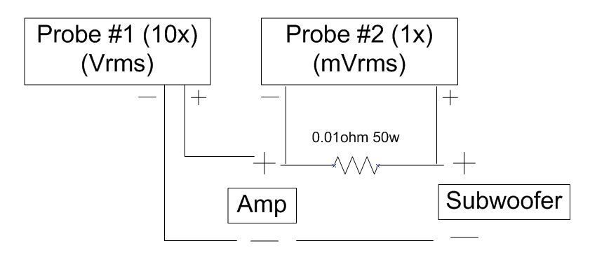
The two probes seem to interfere with each other, and somehow it's actually causing current to run through the probes and heat them up!?!?!
-
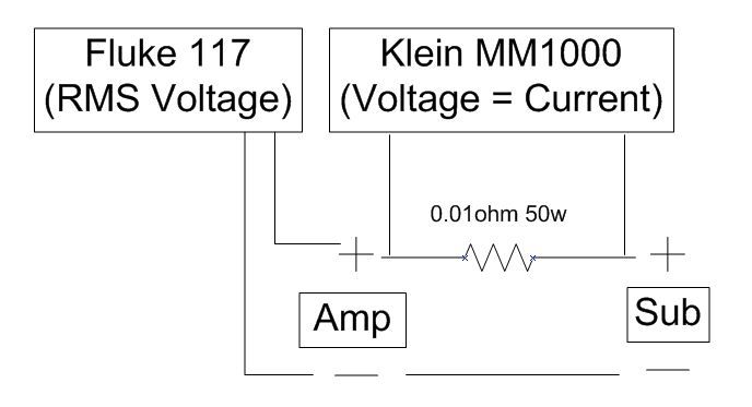
This wiring diagram, where the leads to measure current are across the resistor, is not correct.
When connected this way the current draw on the amp goes through the roof. I'll call my buddy tomorrow to figure out what I'm doing wrong.
The wiring is correct, so I'm unsure if why I'm having issues. I'm going to double-check everything and try again.
-
Here's what I threw together today. Amp connects on the left side.
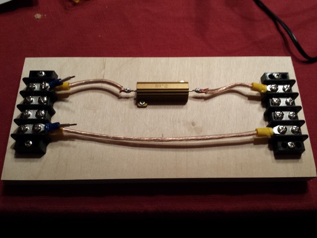
The stubby wires on the left make it really easy to connect a 10x probe to measure Vrms.
-
This wiring diagram, where the leads to measure current are across the resistor, is not correct.
When connected this way the current draw on the amp goes through the roof. I'll call my buddy tomorrow to figure out what I'm doing wrong.
-
What did you end up ordering for resistors? Hurry up and assemble and test it so I can place my order.
I received my 10x probes the other day but didn't pull the trigger on the resistors until my beta tester gives me feedback. I bought this one:
0.01ohm 50W.
Should be good for up to ~6kw at 1.5ohm loads. If you need to measure more power than that, the cheapest way is four of these same resistors in a series/parallel configuration for 4x the power handling.
-
Sweet, the Rigol came with (4) 10x probes.
Maybe tomorrow I'll have some time to assemble my resistor jig and try and measure something small.
-
I noticed that today as well. Supposedly mine can be upgraded since they're all basically the same core unit, at least that is my understanding. But I was leaning towards the Rigol as well until Shreds pointed me to the Hantek. Likely can't go wrong with any of them.
I just pulled the trigger on the Rigol.
It's going to make my head spin learning how to use this thing, but it'll sure be fun!
-
$17 on Amazon. Ordered. Thanks.
On that link for the Hantek you posted is says it's a discontinued product?
I'll probably go with the Rigol. It's more expensive but it comes with two 10x probes and it's software upgradeable to be a DS1104Z ($850).
-
It looks like the Hantek is actually rated for a little more voltage with a CAT III rating of 150Vrms. If it can handle that then I doubt 154Vrms for a few seconds would cause it any problems.
Or I could always just buy 10x probe and call it a day.
-
I just bought this one based on ShredHead's recommendation.
Arggg.....
This Hanek and the Rigol are limited to 150v RMS? My testing with the bridged CC5500 exceeded that dang it.
-
I'm fairly certain I'm going to buy an entry level scope. Maybe the Rigol DS1054Z.
Doing this with multi-meters is clumsy and requires longer sine wave durations since I have to keep track of readings on two different displays.
-
Okay. I wasn't sure what the actual dcr of your setup looks like. You look to be fine for 1.5 ohm. FWIW, the magnitude of the impedance never drops below the DCR. I gather you are running two drivers on each amp channel then with a series-parallel or parallel-series configuration between each pair of drivers and each pair of voice coils on each driver?
Good luck on this. It should be interesting to see what you find out.
Yes, with the two drivers in each box I'll series the coils and then parallel the drivers. With 4 cabinets, each having a DCR of 1.5ohm, I have good ~2ohm and ~4ohm testing options. For the ~2ohm testing I'll be able to share the load between all 8 drivers.
-
-
FWIW, I estimate that the 0.01 ohm resistor will still see 60 W, not 40 W with the amp pushing 6 kW. At least that's in the ball park, but I'd probably opt for more power handling. As lilmike suggested, you can always combine resistors to spread out the heat. Four resistors in a series-parallel or parallel-series configuration will get you the same resistance but 4X the power handling.
Sorry in advance if you don't like the math. For the amp, P_amp = I^2 * (R_load + R) with P_amp being power in watts, I the current in amps, R_load being the resistance (DC impedance) of the driver in ohms, and R is your resistor value in ohms. Your resistor will have to dissipate P = I^2 * R power. These equations combine to yield:
P = P_amp*R/(R_load + R)
= (6000 W) * (0.01 ohm) / ( 1 ohm + 0.01 ohm) = 59.4 W
With R being so small we could "assume" it is zero (negligible), giving a very close (1% error) estimate:
P = P_amp*R/R_load = 60 W
Or for any particular *small* value of R:
P = (6000 W/ohm) * R
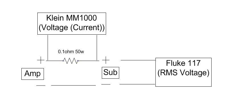
Note that because you are trying to measure the amp power output rather than the power input to the driver (right?), you will probably want to put the volt meter across the amp terminals instead of the speaker terminals. Otherwise, your math must consider the effect of R on the total power delivered by the amp. In fact, your error will be equal to the amount of power dissipated in your resistor. For your 0.01 ohm resistor, this will be 59 W, or about 1%. This is of borderline importance if you are using a resistor with 1% tolerance (i.e., about the same amount of error), but at least you can avoid this error.
Good points.
The drivers that I will be using for this testing are a dual 2ohm configuration, with each coil having a dcr of 1.5ohm. That being the case, I don't ever expect the resistance to ever drop below that 1.5ohm. I see the worst case scenario between 1.5-2ohm.
Good call on measuring the RMS voltage from the amp terminals rather than the sub terminals. This was my plan but I goofed it on my super professional CAD-like diagram.
-
You can also wire your resistors in parallel, you'll get a lower resistance and higher power handling.
I was thinking of that as well, but I need/want to keep the resistance at 0.1, 0.01, 0.001, etc so I basically won't have to do any math. 0.08v will equate to 8a, and 0.10v will equate to 10a and so on. I'll know for sure once I test the rig simultaneously with another meter wired in series to compare the results to confirm it's accurate.
-
This setup looks good. I think you want a resistor rated for more than 50W or a lower resistance. Didn't you say you had a load that dropped down to nearly 1 ohm? Supposing your amp is pushing 80 V rms to achieve 6.4kW into 1 ohm, your 0.1 ohm resistor will see about 8V and will be dissipating something like 640 W. Yikes!
I don't think you have to worry about inductance in the resistor for testing subs unless it's unusually high, like 1 mH or more.
Edit: I'm fairly certain the power dissipation problem is the reason the maximum current measurement in the Fluke and other meters is limited.
Yeah I think you're right. From what my buddy was telling me, most of the time these low impedance wirewound resistors are wound in a way that cancels out inductance anyway even if they don't say it.
I'm going to drop down to a 0.01ohm 50w resistor. Even in the worse case scenario of 6kw with a 1ohm load that should be no more than ~40w seen be the resistor.
-
1
-
-
I'm fairly certain this is how it needs to be wired up, and this looks so good it's scary!
-
Oh snap, an electrical engineer buddy of mine is onto something.
I'll post the details when I understand them, but basically by using a very low resistance wire-wound resistor wired in series with the load, by measuring voltage you're also measuring the current.
Here's the resistor he recommended:
That's the lowest resistance I could find for a non-inductive resistor.
-
1
-
-
I pulled the trigger on the clamp meter. Should be here tomorrow.
I was also looking into a scope and an amp probe, but the probes have the same "accurate" frequency range as the clamp meters.
Similar to a simple multi-meter that can be wired in series with the amp/sub (but is limited to 10A), is a there a device that can be used in the same way but can handle loads up to ~80A? My searches have come up empty, but it's very probable I'm searching for the wrong thing since I'm so green to this.
-
I think I'm going to give this a try:
The specs say it has a "usable frequency" range" of 5hz-20khz, with the most accurate of that range being 45-400hz.
I'll be able to directly compare it with a meter wired in series, so if it's way off I'll know.
If this works out, I'd know the resistance of the load at the peak output levels and we'd have a much better idea of actual power being delivered.
http://en-us.fluke.com/products/all-accessories/fluke-i400.html#techspecs
-
The other aspect you need to look at is frequency. The power ratings for most amps are given at 1,000Hz if I remember correctly. Based on my informal, real-world experience, the IPR2-7500 has more power down low, below 20Hz, which would lead me to the opposite conclusion than yours, which is the IPR2-7500 has the stronger power supply. But it would be interesting to see if Luke's tests would bear this out so we could have some true data.
I was going to compare the 7.5 to my nu4-6000 (basically a inuke-6k when bridged), but I sold the 7.5 with the Ghorns a couple months back...

My living room "make over" (aka the "surrounded by bass" project)
in Bass Gear
Posted
I have the same 5210 surrounds and I really like them.