


3ll3d00d
-
Posts
532 -
Joined
-
Last visited
-
Days Won
28
Content Type
Profiles
Forums
Blogs
Gallery
Downloads
Articles
Media Demo
Events
Posts posted by 3ll3d00d
-
-
You have to respect the differing digital signal levels in the lfe channel vs the other channels. Just summing them doesn't deal with this.the second one was done by extracting all channels then adding them to Audacity and exporting as mono wav in the same 24bit as the original movie files.
-
I can't seem to add the dts file, what program do you use to convert it into a wav file? Sorry I should of asked this from the beginning.
-
 1
1
-
-
It is probably because I hardcoded the z axis range to get a consistent colour scheme. IIRC it used to vary with the data but that made graphs hard to compare visually. A simple fix is likely to be offsetting the data to bring that the level of the peak down to +3, a lot of info fades away into the blue when that happens though. It is quite a hacky script to put it mildly but does the job most of the time!
-
There is a switch to the script that lets you set the spl used as 0 for the z scale (colour range). You can also fiddle with the gnuplot script if required. There is ultimately a limited dynamic range in that colour scheme though so you do have to choose where to focus.
Having said that it sounds like normalisation bit of the script is a bit simple to handle this case correctly

-
completely agree that the proof is in the pudding, if there are no audible artefacts during (normal or spirited) playback sessions then all is good as far as I'm concerned (and if not, will cross that bridge when I get there!). I actually have a spare TD12 though so I keep that and use it for cabinet build experimentation purposes (though I certainly have more ideas about what I could do than time to do it so that one might be on the back burner for some time).
-
I have not come across such equations either. I don't think this is surprising though, for example you don't see much discussion of exactly how a motor is constructed/designed either. Ultimately the universe of materials that are readily available, reasonably priced, easy enough to work with without specialised equipment and suitable for speaker construction seems quite small and the construction method seems as important anyway. I believe the point is made that a panel is a much less complex system compared to a box.
There are some interesting comments from Earl Geddes on diya on the subject, he advocates cld on the baffle and rear panel as well as the braces which are attached to implement a skyhook damping scheme (details in http://www.diyaudio.com/forums/multi-way/276721-best-cabinet-material.html albeit that thread goes all over the shop). There are some other adhesives mentioned in http://www.diyaudio.com/forums/multi-way/284239-seos-dayton-2-way-3.html#post4718307that might be useful too.
There is an interesting article here on building a pre amp for an accelerometer at http://www.audioxpress.com/article/Test-your-speakers-performance-with-this-do-it-yourself-measurement-systembtw (you can buy one from that guy in Greece if you like).
Be interesting to see what you come up with anyway -
FWIW I've been doing some more reading on CLD over the last few days and it seems https://www.amazon.co.uk/Sika-Sikaflex-Polyurythane-Adhesive-Sealant/dp/B003UTA2BKseems a decent option. Objective data is somewhat thin on the ground but here's an example of such a construction anyway - http://www.diyaudio.com/forums/multi-way/218437-3-way-active-time-aligned-constrained-layer-construction.html#post3139996
-
It was the suppression of the peak I was interested in.
On cld, as far as I can see there are 2 practical problems.
Firstly the availability of materials and hence the amount of trial and error required to find something that works well. You probably have more chance taking a short cut here as many posts on diyaudio reference material that seems US specific.
Secondly going from a test piece to using it in an enclosure seems tricky. Some commonly available materials (e.g. various types of roofing felt) make it hard to cut the panel afterwards so actual box construction gets harder and more time consuming.
Nothing insurmountable for sure but certainly seems like a lot of work!
Any thoughts on how you will measure this? Seems like common choices are using a guitar pickup hot glued to the cabinet or an accelerometer.
-
you may have seen them but there are loads of lengthy threads on cabinet construction techniques on diyaudio, so many that it's hard to tell the wood from the trees if you're familiar with the mechanics of it. I don't know about you but it takes me so long (in elapsed time) to build one cabinet let alone a load of different ones that experimenting with different construction techniques just isn't really feasible
 I did pick up one of the accelerometers listed in http://www.libinst.com/accel.htm thoughto see if I could measure what was going on before I build the rest of my cabinets. I need to try to get that hooked up to see if I can measure something reliably (seems tricky in itself frankly but got to be worth a try).
 It would be interesting to see the before and after measurements btw just to see the impact on the measurement to compare against your subjective assessment. I find objective data is essential to make sense of something I can't hear myself.
-
I made my boxes a bit like that. I wasn't sure whether it would have a significant effect on diffraction or not as I couldn't find any tool to model that shape. Once I get the boxes finished then I could compare against my test box (which is just a box) to see how it looks.

-
For my center channel, I'm planning on installing plywood at an angle between each edge of the speaker and the wall to maximize beneficial boundary gain. The speakers are only 225 mm or so deep, for this express purpose.
do you mean so that the shape presented is like this or something else? i.e. the square is your cabinet and the slashes are the angled plywood
______
\ | | /
\|_____|/
-
Edit: It looks like your BMS driver may be exhibiting diaphragm break-up around 17 kHz just like the DNA-360 as evidenced by the considerable beaming there. I used to think this kind of feature was due to a mismatch between the CD exit and horn throat, but better measurements indicate this is break-up, at least for the DNA-360. I'm curious about how much output you can get before that break-up goes non-linear. If you are up to it, you might try doing the sine-sweep tests I did. Obviously, care should be taken when doing the higher level sweeps. I looked for evidence of power compression or excessive distortion after each sweep before going forward, just so I didn't damage anything.
that was some compression sweeps going from 80dB right? I'll give it a go next time I measure in room, I think that sweeping at that level gets me an ASBO if it do it in my garden
-
FWIW I picked up some SEOS12 recently and measured outside with a 8.5ms window, graphs (0-90 degrees at 7.5 degree intervals) are in http://www.avsforum.com/forum/155-diy-speakers-subs/2188265-attempting-3way-seos10-4.html#post43753986
I think you can see the sharper knee I was talking about before if you compare them
-
-
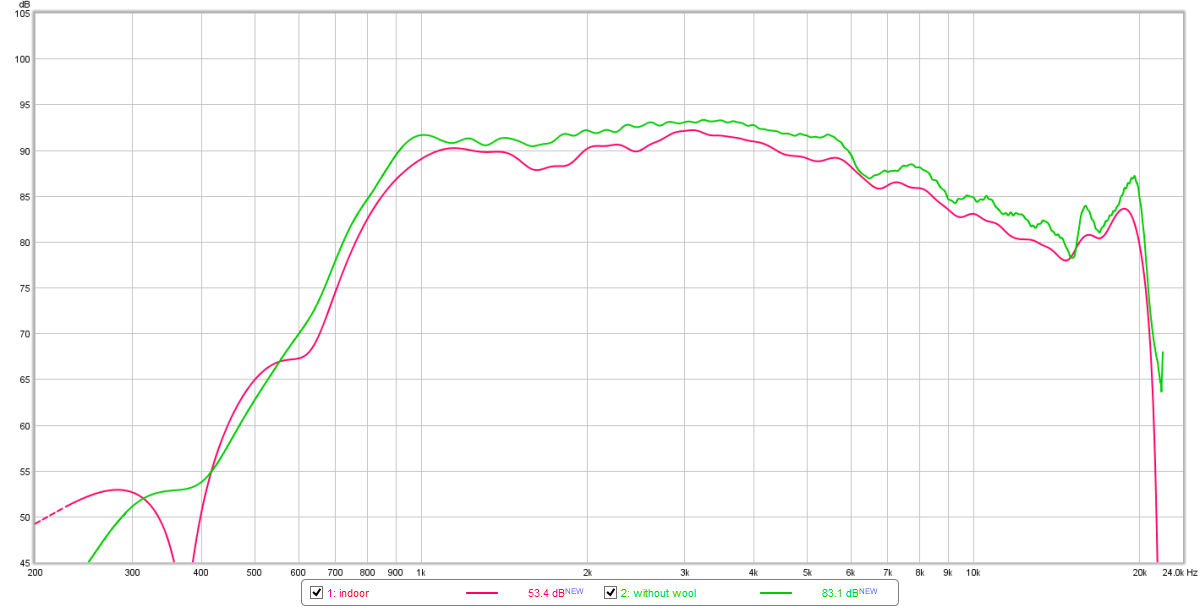
It is odd and I can't explain it. The mic stand, speaker and speaker stand are the same in each measurement so the differences are all in the surrounding environment. Clearly I am missing something but I don't know what.The significant difference in impulse response, from roughly 0.5 to 1.0 ms is interesting to me. Sound moves roughly 1 foot in a millisecond (ms), so whatever is causing the indoor measurement to differ from the outdoor one is very near the horn or the mic. Any thoughts as to the difference here?
-
I offset them a bit to separate them, the measurements were taken at different times and at different levels so were not comparable in absolute spl terms at all. My point was just that the resolution available from 3ms tends to have an effect a fair way beyond 2x the resolution so IME it is worth getting outside. If you look closely then you'll see the knee is sharper on the outdoor one and the 1-2kHz (if not 1-6k) range is generally flatter/smoother. Of course it does ultimately depend on the size of the room (and the magnitude of the reflections after that 1st reflection), perhaps your room is just more amenable to measurement than mine.
I've also seen the baffle impact directivity as you'd expect, in my case it was centred on 800Hz or so but obviously that depends on the size of the baffle.
-
one thing to bear in mind with indoor measurements that have such a short gate is that the low end of the CD response is impacted by a small but appreciable amount. Here's a comparison of mine indoor vs outdoor, same driver (bms4550/seos10) horn combo in each instance


I suspect you'll find this impacts your reading of directivity on the low end which might be important for considering where to cross.
-
fwiw (and I might have posted this before but I don't recall off the top of my head) I wrote a v dirty script to turn REW measurements (or rather, a set of frd files) into various directivity sonagrams -> https://github.com/3ll3d00d/directivity-utils
it just needs cygwin, gnuplot and awk (or just run it on linux)
perhaps you'll find it useful for visualising & comparing directivity (I find it makes anomalies jump out at you more so than viewing all the raw measurements as FR charts)
-
1
-
-
DATS sorta worked with W7, but it was squirrley. Now that I'm on W10, I can't get the DATS to calibrate properly or even measure the same driver (or resistor) repeatably. I'm not impressed with it at all.
My settings are correct. I've tried updating to the latest software (for even more $$$), still no joy. At this point, I'm done wasting time and money on it.
FWIW (probably not much as you have multiple other ways to measure!) there was a thread on techtalk about that, various users had similar problems but settings were worked out that fixed the problems.
-
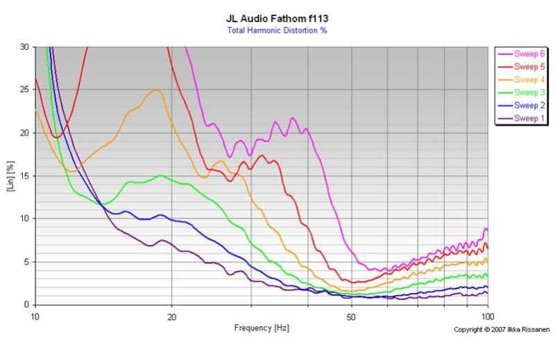
I doubt it is about that transition, the links are to a Finnish file server so it looks more likely they never hosted it in the first place. But anyway the test method is explained in http://www.hometheatershack.com/forums/subwoofer-tests-archived/971-subwoofer-tests-explained.html
-
google image search can find a few of them

-
unfortunately the graphs seem to have gone AWOL -> http://www.hometheatershack.com/forums/subwoofer-tests-archived/8152-jl-audio-fathom-f113.html
not sure why HTS didn't host the graphs themselves, seems a bit of an error
-
I think that is a bit of rather misleading marketing to put it mildly.You are right, this is only a (smaller) 13.5" driver, but there is 4" woofer excursion giving 6.3L (386 cu inch) of effective displacement, which outperforms many larger size drivers.
If you look at http://www.jlaudio.co.uk/13w7ae-d1-5-car-audio-w7ae-subwoofer-drivers-92116 (which afaik the fathom is based on, at least a refined version of it anyway) then you will see quoted xmax of 32mm and a suspension that is capable of 4" peak to peak travel (so 2” one way). They appear to have taken that 4" suspension peak to peak and turned it into a displacement figure when applying it to the fathom.
-
the soundtrack is pretty lame and it is rather long, not that that is news to anyone who has watched any LoTR film (especially those directors cut versions), but I don't think it is *that* bad. There are certainly many far far far worse movies out there anyway.

 I did pick up one of the accelerometers listed in

The Low Frequency Content Thread (films, games, music, etc)
in Bass Content
Posted
it is described in the link in my earlier post http://www.avsforum.com/forum/113-subwoofers-bass-transducers/1333462-new-master-list-bass-movies-frequency-charts-post23468771.html#post23468771