

Ukko Kari
-
Posts
125 -
Joined
-
Days Won
14
Content Type
Profiles
Forums
Blogs
Gallery
Downloads
Articles
Media Demo
Events
Posts posted by Ukko Kari
-
-
One way to cure diffraction is to flush mount the cabinets in a baffle wall with a layer of absorption, like 1" thick.
Realistically, larger radius corners should have been used on my boxes, but 1 1/4" is getting a bit hairy to handle in a hand held router even with a large add on baseplate, and 1 1/2 is about the limit without going to MDF substrate and using machined corners.
http://www.tapeease.com/cabinet1.htm
I could have gone the skeletal route with multiple layers of thin plywood instead, ending up with curved sides, large radius on the baffle. Did I mention the dust was *incredible* when routing all of the corners to 1 1/4" radius? Doing this outdoors with a slight wind, it was still problematic, it was like it was snowing wood dust out.

-
9 hours ago, SME said:
I had the same problem with my mains, which are at 45 Hz vs. closer to 55 Hz (to be used with subs) to limit excursion related distortion. My ports have the two flared ends connected directly together so can't really go any shorter. It's not a big deal though. These speakers handle movies at reference levels without flinching. I'm thinking of enhancing them with low-mid/MBM units to create a kind of shadowed pseudo-line array. With those in use, the mains woofers won't be pushed nearly as much.
At the end of the day, you have to ask yourself is the juice worth the squeeze? Additional amplifier channels, more complexity, an additional surface for diffraction from your main woofer.
-
Perhaps juggling chainsaws would be easier than picking trade-offs. Baffle width, roundover size, cabinet depth, height, volume, adequate port area, bracing, ability to get cordless drill inside enclosure for installing the pocket screws on the last side... portability, ease of assembly, etc.
-
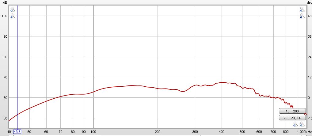
Mic 1/4" from top woofer dust cap:
Edit: I don't recall if eq and crossover were enabled, it's been a while since this was measured. Might have to disable the DSP and re-measure this.

-
I had hoped that the tuning would shift up enough by shortening the ports 2 inches, but their proximity to the side walls and floor of the enclosure means that they are acting like they are much longer than they physically are.
It is a bit of a pain to finesse the port length, but I would like to get the tuning point up just a wee bit higher. I can live if they aren't 40 hz.
-
2 hours ago, SME said:
Some of the phase zero crossings still aren't correct either.
I also checked for excursion minima with sine waves at high levels. With the shorter ports, excursion minima was 34-34.5 hz. We can debate minutia all day long, but that doesn't change much. When the voice coils have some heat in them, the impedance will shift as well.
-
As an experiment ( per Lilmike ), I hooked up a pair of UCA-202's, output on one, and measure on the second to get rid of the cross talk issues. Apparently, the absolute value for impedance is off, but the <20hz cross talk is gone.

-
Had a bit of time today to pull the lower woofer, wiggle the ports out of the baffle, shorten to 8" long, installed they are 8 3/8" total.
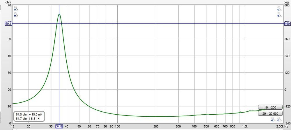
Net interior volume went up by 0.11 cu ft, to a total of 9.63 cu ft. I had not saved the impedance .mdat prior, but looking at the screen shot, the upper impedance peak fell a small amount, as it would when the box volume increased.
Removing 2 inches on each port only raised the tuning ~ 1 hz, observed excursion minima was at 34-34.5 hz. I also found a leak around a screw during testing, the foam seal had compressed some since assembly.

-
The closest I could place the cursor was -0.9 degrees, yes it coincides with the peak on the right, but the others are shifted some. I get 0.5 degrees at 0.7 hz above the left peak, and centered it's already at 20 degrees.
-
Here's a screen shot with the phase:

-
13 minutes ago, SME said:
Does the impedance jig capture phase accurately? If so, then the port tune frequency will be precisely at the phase zero crossing.
Based on your post, I would have to say no, since the 0 crossing would be around 24 hz, based on the phase reported in REW.
-
Again, same measurement of the co-axial through the autoformer, however this time with only -6 db attenuation.

-
And now for the interested, the same measurement as above through a model 3636 autotransformer at maximum attenuation, -12db.

-
BMS co-axial through passive network:

-
Pair of woofers in parallel, approximately 20 feet of 14awg speakon cable into the box: ( didn't account for that in Rleads box of REW)
Note, port length unchanged, 33hz excursion mimima +/- 1/2 hz observed. Will be shortening ports to bring the tuning up when I get time to do some more measurements.

-
Built Lilmike's impedance jig and took a few measurements.
Raw 15PR400 hooked up with short 2 foot leads:
-
Coming soon ( in the next month or so, busy with work and life ) impedance measurements, thanks to Lilmike.
-
I'm sure someone could find an application for this, but the more I think about it the less it seems worth the hassle. Wouldn't it be easier to series the load and use the amp in bridged mode like you normally would, and skip the parallel inputs and reversing the polarity on one of the outputs?
Even in the best case scenario of a 15% gain, we're talking about a fraction of a single dB of gain.
The real answer is it depends. I agree that it may only be a small fraction of a difference. It would be interesting to note the input power to the amplifier to see if the efficiency / breaker utilization changes any, which may be a bigger deal for large systems with racks and racks of amplifiers running off a generator, or in a venue where power is subject to droop. ( older wiring, smaller services )
-
I have found the ports are acting like they are almost the full depth of the cabinet. I started the generator in REW at 25 hz, then raised the volume level until excursion was a few mm, then in 1 hz increments raised the frequency, checking for excursion minima, which ended up at 33 hz, +/- 1/2 hz.
I had a feeling that tuning would be lower than expected, from the proximity of the ports to the enclosure side walls, and each other.
Having calculated the volume of the bracing, and ports a few times, using the manufacturers supplied volume on the woofers, along with a good estimate of the horn displacement along with the compression driver, I can confidently say the internal volume of the enclosure is 9.52 ft^3. +/- a small percentage.
Dual 7 5/8" ports, 10" long should have put tuning at 40 hz in 9.52 ft^3. When I have a chance, maybe next weekend, I will pull both and shorten them to 8" to try and note the result.
-
I was asked to test this over 2 months ago but I've been a huge slacker:
The basic theory is that if an amp is driven in stereo and both channels are producing the exact same signal, both channels are also drawing current from the power supply at the exact same time/interval. The author of the article claims that if you parallel the inputs but flip the polarity on the input of one of the channels, causing the sine waves from each channel to be exact opposites, the channels are now "taking turns" drawing current from the power supply.
For these tests I used a CC4000, wired my test rig for 3.4ohm per channel, and used a 30hz sine wave for a duration of 2 seconds. I pushed the amp as far as it could go while still producing a clean sine wave.
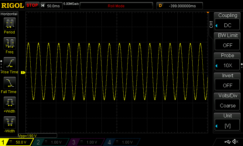
For test #1, I used an XLR y-splitter cable to parallel the same signal to the inputs and the amp was in stereo mode.
For test #2, I put the amp in bridged mode and didn't make any changes to any cabling. According to the article, all this switch does is reverse the polarity going to the B channel of the amp.
Results:
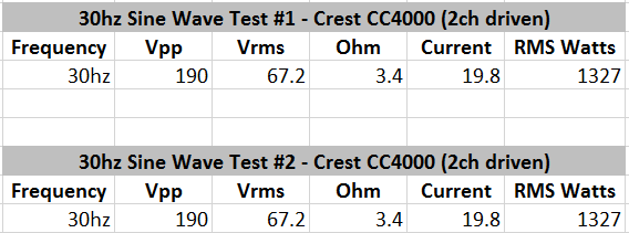
Test #1:
Test #2:
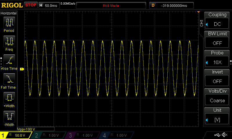
Really no difference at all, certainly not the 5-15% increase claimed in the article. In fact, I think test #2 has slightly more distortion in the wave form when pushed to the same 190Vpp.
I read that article many years ago, and in some cases, it can be applicable. Keep in mind that you are also driving essentially a dummy resistor load, and the results may be different driving a reactive load, where back EMF is reflected on the power supply.
-
 1
1
-
-
It's all over the place. One day it's sunny and 65 and the next it's 35 and raining. We had some sub 20deg weather just 3 or 4 days ago.
But I'm getting prepared for the next available window.

I wish it was 65F.... tonight the forecast is close to -20C... [ -4F ] No outside measurements for a while here.
-
Please post the measurements and a follow up when you do get around to the measurements.
Are these speakers intended for your home audio / HT or are they going to be used for sound reinforcement / PA?
These will be primarily for HT, however I may want to use them outdoors at times in 1/4 space. With the lightweight drivers, they aren't that bad to move.
-
I'll second Ricci here, not sure that 2R load is a great idea. Sure, it is a ported cabinet, so the average impedance is much higher, but that minima at 40 Hz might cause issues.
Have you measured impedance of the actual build yet?
No, I have not measured impedance yet, when I can get to it, I will.
-
Hello Ukko...Hell of a first set of posts. Information overload!
I like your choice of drivers for this project. The XT1464 seems to be quite popular and performs well. It seems like your cabs are built and assembled already , so you are at the point of fine tuning with DSP? Will you be finishing the cabs afterwards?
I'm curious but why parallel the woofers resulting in minimums near 2ohms? Why not run the drivers in series for a much easier load on the amplifier? The pair of Faital's in a large vented cab should be very efficient and won't require much voltage to hit very high levels even if it is an 8ohm load.
One cabinet has been assembled at the moment. Yes, at the moment working on measurement, waiting for nice warm weather both to measure outdoors, also to order Duratex when the risk of freezing has passed.
I am not against a series connection, it would increase the applied voltage and cut wire losses, increasing damping factor. A warm voice coil increases in Re, and if my math is correct, at just 50C, the VC Re would increase to 3.724 ohms.


Faital 15PR400, BMS 4594 MTM
in Speaker Design
Posted
What is a good horn in your experience? For a common 90h x 45v horn of 12 inches width and 6 inch height, the vertical polar pattern will widen below 3.7khz, exceeding 90 degrees at just below 2khz, according to this article:
https://www.prosoundtraining.com/2010/05/24/understanding-horn-directivity-control/
Even the 18 Sound XT1464 is 'small'. Used with other elements in a vertical 'array' of 3 elements [MTM] leads to increased directivity in the vertical dimension, even when the pattern control is falling from the horn.