


Audiovideoholic
-
Posts
12 -
Joined
-
Last visited
Content Type
Profiles
Forums
Blogs
Gallery
Downloads
Articles
Media Demo
Events
Posts posted by Audiovideoholic
-
-
Ok. Think I’ve got it nailed down finally.
wow. Some basic mistakes on my part and some wrongful teachings by others in the past...lol. They tried though and that’s more than most so can’t really complain.
Here are my results now that I’m using driver sealed volume for both drivers and leaving those other two Hornresp boxes empty (Vtc/Atc).
it looks correct now!
i will do all the options and post pics and parameters if you don’t mind double checking my findings once I think I’ve nailed down the designs.
How do we use the feature with the AE drivers? Since Ricci gave those input figures how does it work with the other drivers?
bests
Alex

-
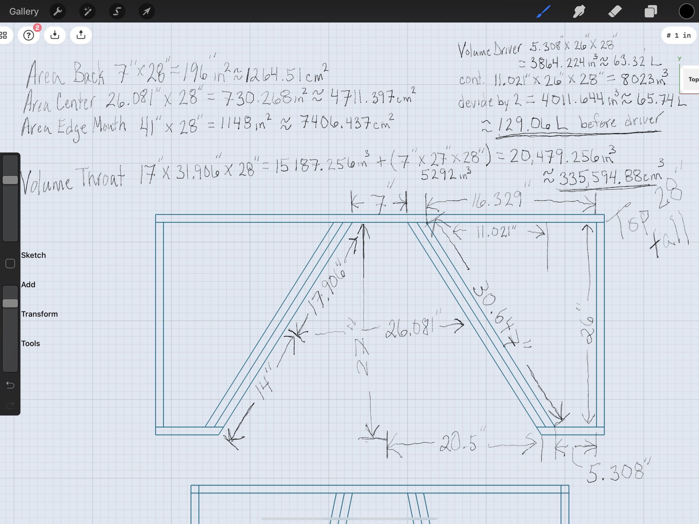
For this one pictures below with a 32 degree Angle (64 degree total) I’m getting way different looking results than yours.
This is the cabinet I used for the data input into the above Hornresp pics.
note it’s a Top down view and it’s 28” tall for interior lengthsbests
alex

-
Trying to edit pics. I’m computer illiterate


-
Testing pics. Too big and rotates when change size, uggh.
sorry don’t know why it rotates them.

-
Ok. I’ve gotten the Inductance truck to work, yay!
So why do you have Vtc and Atc both blank in your models?
i am getting a slightly different graph for some reason as well.... do you see why in these pics? I used Ricci’s data from above.
I do notice the actual horn/slot chamber volume being different in these than what I was doing previously according to the diagram schematic.

-
Ok. I see what you mentioned about the 60* and how that takes the peak out for less distortion.
I will have to double check the sealed volume for that model to make sure I’m looking at the correct design.
on the sealed volume note, when modeling does one put in the single cab/driver volume or entire system volume(double in this case)? I thought this was only modeling one driver of the two? If it’s modeling the total system then the voltage would also need to be doubled when checking the excursion?
Thanks again!
alex
-
Ok. I tested to see if could post pics from my phone since I don’t have a hosting site.
no issues with posting. Super easy thank goodness.
I will get all the cab dimensions pics with dimensions and annotations for both the angled and 90 degree designs that have the maximum lengths so can shrink if necessary.
I have both the smallest and largest dimensions for both types of designs that will allow the lengths of the rear parts of the drivers’ makeups, supposedly. I know I do for the AE drivers but SI I am using 13.5” mounting depth based on hearsay. The AE is from true specs so know those are exact. We will use 13.5” mounting depth for the SI 24 and if need be I can correct later as that won’t be a big deal.
I’ll get all the 24 stuff posted when have a few minutes to notate everything so you don’t have to figure values.
bests
alex
-
-
On 8/18/2020 at 5:32 PM, peniku8 said:
Welcome to the data-bass!
Do you have a schematic of the cab(s)? I'm unsure if you're planning to
- Build two sealed 24" cabs which will be placed with the drivers facing eachother, creating a slot similar to an IB manifold in the baffle wall
- Build a single cab with two 24" drivers in a similar configuration to the above, which basically creates a band pass
As for the AE drivers, it sounds like you're planning on doing the latter, but you mention that the drivers would be placed at an angle, so I guess kinda like SKHorn without the front panel and sealed, plus I guess the intended angle would be more like 45-90°?
I’m not quite sure why the reply is making me quote but will proceed.
thanks for the help!!! This has been driving me crazy trying to figure out!!!!
i cannot use ported designs but can appreciate them none the less.
can you try to modify the angle of the slot from rear to the baffle face and see if my predictions were correct?
i just used the -5dB points at a high voltage and compared the two(angled interior driver baffle to 90 degree interior slot driver baffle). The angled baffle gave me the higher spl at lower frequencies by about 5Hz..
the 90 degree/parallel Face to Face alignment was -5dB at like 40Hz and the angled interior baffles was -5dB at like 35Hz.
since I will be using these for LFE duty and mainly concerned with the 2Hz-40Hz range with them I would like to make sure I choose the correct method for aligning the interior baffles/slots.
what’s the correct term for this interior baffle when in this alignment so that the terms can be kept straight when speaking of this design or other similar designs?
i can change the sealed enclosure space, angle of interior baffle, and slot chamber area/volume no problem. I can also use as much power per driver as possible as I will be matching the amplifier to the enclosure/driver system. There are plenty of 240V options from 5000 watts per driver at 4 Ohm down to 2500 watts at 2 Ohms.
I figure maxing out excursion with smaller enclosure along with the face to face compression will be the best way to align the system but not positive about this?? I can just set voltage limiters for this and test to make sure the math matches up in real life.
again I really appreciate your help and would appreciate if you would allow me to send you a paypal tip for a token of my appreciation.
I had no idea about the wrong data I was using for the area in front of the driver and nobody over at AVS knew either being that the ones most familiar with Hornresp didn’t use that figure either when they were teaching me the values.
heck I even sent this design to a speaker designer As a commission and they didn’t come back results anywhere near what I have done on my own more less what has been found wrong with what I was doing that was caught here so feel very fortunate!!!
DIY and DIY Subs have huge advantages when they are done correctly but some designs can more challenging when using more than 3 segments or other less unorthodox alignments.
I will get the data for the 18” drivers after I hear what method works best for ULF as I would expect the opposite might work better for the 40Hz/50Hz-120Hz range? Would that be the ideal starting point, the opposite alignment (angled/90degree)?
Bests
alex
-
17 hours ago, peniku8 said:
Welcome to the data-bass!
Do you have a schematic of the cab(s)? I'm unsure if you're planning to
- Build two sealed 24" cabs which will be placed with the drivers facing eachother, creating a slot similar to an IB manifold in the baffle wall
- Build a single cab with two 24" drivers in a similar configuration to the above, which basically creates a band pass
As for the AE drivers, it sounds like you're planning on doing the latter, but you mention that the drivers would be placed at an angle, so I guess kinda like SKHorn without the front panel and sealed, plus I guess the intended angle would be more like 45-90°?
They are both the same type of enclosure. 2 drivers per enclosure separated by a slot and each driver has its own sealed space behind it.
Think of two drivers facing each other firing at each other into the same “Slot”. Basically two drivers being slot loaded. They can be perfectly parallel or angled where the drivers are closer together at the rear of the enclosure creating a wedge type of alignment which changes the compression against the drivers I’m guessing.
Or the speakers can be 90 degrees to the rear baffle which would place the cones in parallel similar to how IB manifolds “look” but the actual space behind the cones is an enclosure.
Here is Procella’s wedge type of design.
https://procella.audio/product/v21-2/
Rob Hahn’s big Baffle Wall uses Keith Yates subs in a 90 degree to the rear fashion. Here-
http://keithyates.com/ubersub/
He uses the actual baffle wall sections as the sealed enclosures for each pair of drivers and slides them into the wall mounted on his metal faceplate design which is really cool.
Here is my original thread that explains the input parameters of what each function in Hornresp means when modeling 2 drivers into the same slot without any barrier between the drivers
https://www.avsforum.com/threads/si-24”-face-to-face-driver-arrangement-help-please.3105066/page-2
Here is my thread showing all the inputs and cabinet for the 24s.
So you were thinking correct. And yes I have drawings and even all the Hornresp info to input to give head start no problem.
All the 24” stuff is in that last link. All Hornresp data and enclosure stuff. If we get that one taken care of will move on to the AETD drivers.
bests
alex
-
Hi all. This is my first post here and hope this is the correct place.
These cabinets are being placed into my baffle wall for HT. All drivers are already purchased but need to fine tune these cabinets with inductance features now available in HornrespI am familiar with Hornresp and Winisd but am needing help with a cabinet for ULF and a different cabinet for Mid Bass/Bass modules.
The ULF cabinet will be 2-SI 24” Mkiii drivers in a sealed cabinet Face to Face alignment. I have modeled them but am not able to use the inductance features that are now able to used so would be greatly appreciated if someone could either model them for me or I am more than willing to pay for someone’s help as I’ve offered this option over on AVSForums with zero luck. I have a thread over there asking about my models in Hornresp but no input from anyone. These I want to optimize for as low of a response as possible. I have as much power as needed with 3 dedicated 20amp 240v outlets in my media rack closet.
I can give all the parameters that I’ve managed to come up with if anyone needs a head start finding all the cross sections etc.... There will be 2 total cabinets for a total of 4 24” drivers in this arrangement. I have 6 total 24s but the other two will be used in a different location on the baffle wall.
The second cabinet will be using the AE TD18H+ in a sealed cabinet Face to Face alignment. These will be used as 4-ways to my Quested LT20s under each LCR. Mark Seaton has given me a head start of placing them in roughly 75L and an opening of 22” at the front. I don’t need any help in creating the physical cabinets as I can work backwards from any given data no problem so anyone is free to just use the wizard to give me the best angles/areas. These I want to optimize as mid bass and lower extension for the LT20s so say anywhere around 30-40Hz up to 120Hz or so but just try to let the data provide the best response range. From my understanding the wedge manifold design will limit the upper end response. And I think the 1/4 wavelength will start kicking in around 130Hz or so with my available space. The height ends up getting me to the 130Hz 1/4 wavelength off top of head from memory.
Thanks for your time and hope someone is able to help me with this last hurdle. I can provide all my data I’ve already used if needed but think using the wizard will most likely be the easiest then I can just work backwards from there.
Bests
Alex


Help Please With Face to Face Sub/Mid Modeling
in Bass Gear
Posted
Ok. I’ve been messing around with the Wizard and believe (????) that maybe by forming the rear of the mouth closest to the actual driver as possible will affect the “LOWER-END” of the FR more than anything else I can manipulate. Driver enclosure volume, angle of drivers facing each other, etc... It seems like the more narrow the rear section is the higher the peak in the response is toward the lower end.
Is that a fair assessment on your part as well? This leads me to believe that aprox 200 Liters per driver, aprox 60 degree angle, and a formed rear section similar to my drawing in the attached pic in this post will be best. Does that sound good?
These alignments should allow well over 100 volts into each driver without worry.
bests
Alex