peniku8
-
Posts
476 -
Joined
-
Last visited
-
Days Won
56
Content Type
Profiles
Forums
Blogs
Gallery
Downloads
Articles
Media Demo
Events
Everything posted by peniku8
-
I love that PDF, it's comedic and informative at the same time! "Do not confuse any other frequency with kick, it is 91Hz" lol! "The first things you need are some familiar test tracks that you have played on a variety of different systems." I'd like to add: the more spectral content the track has at any given time, the better. Aka "Apocalyptic Feasting" by Brain Drill. Venues and Hosts will love you when you blast that song for soundcheck. I also see RTA mentioned quite often, but never that you'd supposed to send the return of a measurement mic into one. I don't like equal loudness contours, as it's based on sine waves and research using bandpassed noise have yielded different results. He also takes a very different approach to handling equal loudness contours. Instead of always trying to achieve a flatter reproduction depending on the listening level (like what the dynamic EQ function on AVRs does, which I absolutely hate), he makes the listening experience at high levels sound like you'd percieve lower SPL levels, which is kinda the approach I'm also taking (and basically the opposite of the AVR approach, which basically makes high SPL listening even mode midrange/lower treble centered).
-
@SME I had live bands in mind with the 60Hz kick drum range. Studio recordings are very different from live acts. They'll still vary ofc, as not every instrument is the same, but typically the kick lands in the 45-70Hz range. Also keep in mind that the signal processing chain (including the mic) will result in the 100-1000Hz decade being attenuated quite a lot in most modern mixes. It doesn't sit in the mix very well. Yes a natural Jazz recording will likely differ, but anything I've ever experienced live (be it cover music or the actual acts from Robbie Williams, Pink Floyd, Queen, Iron Maiden, Judas Priest and dozens of other Metal bands) followed that principle. I also agree that a wide range rattles the chest, but I disagree that quality of tactile bass is tied so linear frequency response. I get the feeling that TR is tied to voltage sensitivity more than the actual FR. So yes, in perfect free field conditions the TR might track the FR while both are linear, but in a room where you start cutting the modes, the frequency range that gets less cuts will feel more pronounced in TR. I cut more between 10-60Hz than I do above and I get the feeling that the range that I do less cuts in feels more pronounced in TR, even if the FR is linear. Could also very well just be the resonance frequncies of my couch or my own body, who knows! I mainly use Waves' RBass to generate sub-harmonics in the studio. That plugin is pure magic and I love it! When I notice the lack of bass in an instrument during soundcheck of a live show, I often just send it into my suboctaver channel, which does exactly what it sounds like: it doubles the signal once octave lower, which goes through a LPF to not interfer with the original sound too much. I basically always use it when the drummer is playing a Cajon instead of a full sized kick drum. The band I'm "touring" with has a Cajon that kicks at 90Hz. The suboctaver adds a nice fat 45Hz to it and oh boy is it nice! Even the band basically immediately started questioning me about it after the first gig about how I made the kick so massive, it's great.
-
I've been to concerts with high volume sustained output between 80-120Hz. These were not the most pleasant concerts I've been to. I generally think that the power requirement below 70Hz will be larger than that of the upper bass range. But I think the octaves of 10Hz would also be interesting as it classifies the bass pretty well imo. 10-20Hz content for the cinema crowd, 20-40Hz as sub-bass and 40-80 as the typical high power bass range for live events. Sub 10Hz requirement seems to become less sought after, now that so many people use low-power TR devices instead of a pile of sealed subs. At least that's my impression on AVS atm. I too used to just turn up the sub channel to get more bass before I knew better. It's an easy way and often the only way with simple analog systems to shape the response. Luckily dsp amps are finding their way into entry level PA systems, which gives newbies a lot more flexibility. I like the noise idea. Most high power amps will generate noticable hissing if you're less than 3m away from the CD (on axis ofc), but it won't be super noticable any further.
-
@SME The test files will ramp up, but not super hard, but also not as soft as some others do. Probably 6db gain per cycle, REW does 6db gain over 3.5cycles, which is fine for 1khz testing, but might already be an issue with 40hz. I wanted to test 60Hz since that‘s around the center kick drum sound, especially for live music. And I don‘t think 80Hz is too useful/realistic as the crossover point of any live PA will very unlikely be any higher, so 80Hz would already be shared by two amps 50:50 at an example of an 80Hz bw crossover. I think I‘ll do octaves from 60 to 7.5 then. But I don‘t know if I can get useful results that low, we shall see.
-
I was guessing that if an amp does 20 cycles at 1Khz at a certain power, it would do 1 cycle of 50Hz at the same power. Are amps that bad at keeping up current for longer intervals? I think I'm gonna go with 10s test duration. Even the intense EDM song I looked at had a crest factor of 6-7db. And the dubstep sine waves are usually not full power because some headroom is needed for kicks. And I certainly don't wanna blow up any amps anymore. Especially when I'm testing amps north of 5 grand like that LA8 (although I doubt that that amp would NOT have very good protection circuits). I don't like the CEA-2010 test since it hides the temporal aspect and ties it to the frequency. I will most likely create some custom test files, basically sine waves which ramp up quickly. I can do a visual overlay so you'll see where exactly the amps drops off in output voltage. Also, CEA-2010 does not contain a single full output cycle. Just one peak will be at Vmax and the neighbouring peaks will already be a little quieter. Most amps I've seen have HF protections which mute high output above typically 10k anyways. I don't see why high output at 16k would be useful, as the strongest CDs do like 200W, so even if you have like 2 to 4 of those like in very high power line array elements, you don't need 10KW or anything for that. A scenario like that usually has one amp channel for one speaker. I was thinking about doing octaves in the bass region: 60Hz, 30Hz, 15Hz. Any higher than 60Hz would end up in the typical crossover region, so not super hard on amps typically and any lower than that will probably not be possible for me to get super accurate results for. One can gauge single digit results from the 15Hz performance anyways.
-
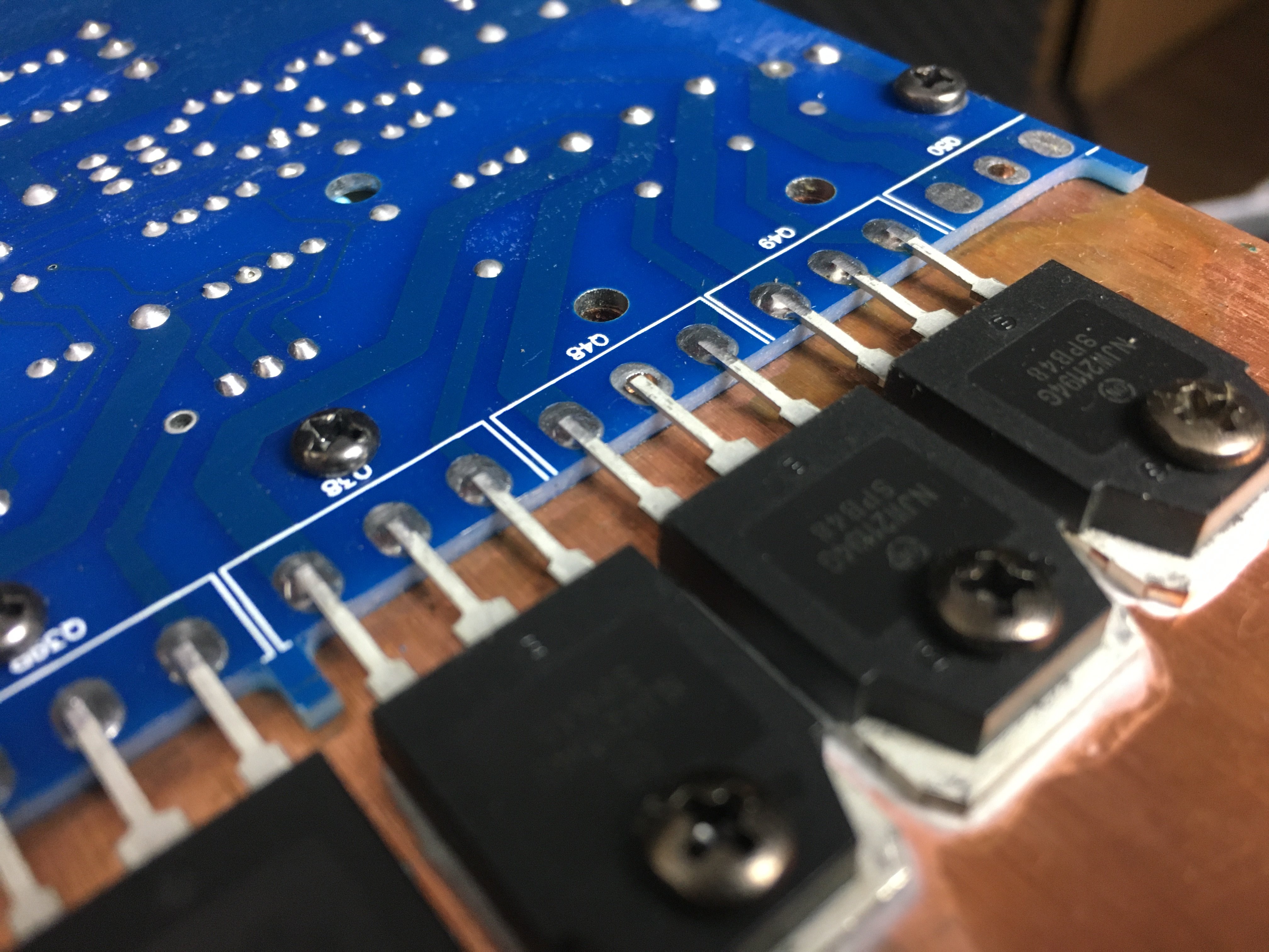
Yea the blue PCB sure looks more modern 😄 I don't know how the FP-13000 (14k)'s internals compare to the 10kQ (which is I guess the amp in this picture since there are 4 amp modules), but to me it seems like at least the Sanway clone (and a few others I've seen) took the 'more is better' approach and squeezed more caps and seemingly slightly larger heatsinks in. What wierded me out was the amp starting to smoke when I had it on for half an hour with the fans disconnected. Seems like the 150W or idle power draw is dissipated around the rectifier area, but I couldn't find where the smoke came from since the case was closed at that time. No visual clue remained.
-
I have since updated my device OS and that seems to have fixed the issue. All good 🙂
-
Bending the leads through the holes wouldn‘t be practical for machined assembly, I doubt anybody would do that. Q50 is probably installed on the Fp14000. The FP13000 is exactly the same amp with a few components missing. Probably the transistor there and two caps for the PSU.
-
One funny thing I‘ve noticed thou was one of the transistors not being soldered to the board. I‘ve corrected that now


-
The relay seems to be working just fine. The Thermistor that broke seems to be the issue. It blew its ceramic shell, but the (soldered out) resistance still measures the value stated in the data sheet. My conclusion was that it reaches 0 resistance way too quickly now, which basically bypasses the soft start feature of the amp. The current spike trips the breaker. Amps tested are the FP-13000, a KMT LC1300 (old German 3U amp) and the popular (at least in Europe, particularly Germany) t.amp TSA1400 and the t.amp TSA4-300. Amp I have not yet tested are the Sanway DP10Q. Amps I could probably have easy access to for testing are a tamp E800, iNuke 1000, l.acoustics LA8 and a Crown XTi model I forgot
-
Yea I didn‘t particularly like that either. Shouldn‘t happen even if the amp is 7 years old. But it did 1 minute of 4KW output before it blew up!
-
Sanway FP-13000 1x2Ohm
-
I updated the first post with some info. More coming soon. I have hopes on the amp. The mains relais switches on the power supply with a delay. The amp shorts and trips the breaker as soon as you flip the on switch, which means that the PSU doesn‘t cause this. It might still be good. I‘ll get a replacement power input board (30$) and hope for the best.
-
Did you read my last post and look at the graph? It's not 80ms, it's 260ms. It then gradually drops to 4.5KW over a span of another 500ms.
-
@kipman725 Interesting concept, I guess you're going into a similar direction as what current high power PFC amps are doing? I like the trend of new amps to come with a universal power supply. The new Powersoft amps work with any input voltage from 70-270V iirc, single bi and triple phase. Fully equipped with PFC, relatively high efficiency and the option to set a breaker in the dsp. As I see it, only increasing efficiency and stored energy will allow for more output with high crest factor content. And yea on the amp, it was my main HT amp. I swapped it for one of my spare amps and lost ~8db headroom. The SKHorn is efficient in the upper register and room gain of my small room helps with the lower end of the spectrum, so the single sub I'm running will probable be fine. Gramps is currently investigating the remains of the amp to check for bad parts. I'll swap out the entire broke board and see if I get it running again. If that doesn't do it I'll see what if would cost to swap the entire PSU. I suspect the mains relais to be the point of failure, which would be an easy fix. @klipsch I've read about it blowing up. notnyt is actually the guy who sold me the Pmillet Soundcard Interface, which I'm using for my tests 🙂 @Ricci I had it on a C16 breaker, which tripped after 14s. When I hooked it up for 32A230V it blew up... The clone muted its output (DC protection) a few ms into the 1Ohm test. Maximum it did was 3.5KW for half a cycle. It also muted the output when I set my test frequency to 10khz instead of 1khz accidentally. I do all tests with a 1khz sine wave. "If the amp can do 10 cycles at 1khz it can do 1 cycle at 100Hz" is my logic, so the 1khz test allowed for a 1ms "resolution". I will publish the results as seen below. The graph below is the first I've finished. @SME I evaluated the results of the Sanway amp and noticed that the 2Ohm power sustained for 260ms, not 80. 260ms is very nice imo. Idk what it would look like with both channels driven, since I couldn't test that anymore. The graph stops at 13.3s, because the breaker tripped. I won't test the amp again on a 32A circuit, even if I get it working again. I tried to do all tests at a total duration of 2 minutes, but out of the 4 amps I tested this way one was fine, one started smoking, one started smelling and the clone blew up. What would you guys suggest? Is 2 minutes too long? Not useful info anyways? Not all amps have superior safety mechanisms built in like maybe a Powersoft amp does... I had a look at Martin Garrix's "Animals", which is a pretty bass intensive song. The longest duration of more or less uninterrupted bass was 28 seconds with a pretty low crest factor. Even most heavy bass dubstep songs have something that resembles a chorus and quieter sections in between, so I think a 30s sine wave test should cover most of it. I'm not in the situation yet where I can afford to blow up half of my amps because I want to test them at their absolute limits. I'm hoping to have a write up on my testing methodology posted after the weekend and maybe some final results already.
-
Well those amps were not made to deliver maximum ouput for anything longer than you'd see with typical live music. I'll check sustained ouput later, but it's above 4KW from the PSU for sure. Well until it explodes.
-
Sad times, my clone amp exploded while testing. It tripped my C16 breaker on 230V after 10 seconds into any load except single channel 8Ohm, so I hooked it up to a 32A connection. Didn't like that 😪 But I can already tell you that it (Sanway Fp13000) does 7.5KW into 2Ohm for 80ms (one channel driven). It sustained 22A power draw but I haven't evaluated all results yet. Seems like just the main relais is broken, but I exploded the entire circuit board during troubleshooting, so I need to get that replaced. A coil, a Thermistor, two Resistors, one fuse and the PCB itself blew up. The amp is 7 years old. This happened during a loopback measurement of the audio interface and THD gradually rises over a span of ~15db.
-
So far one amp specified to 2x800W into 2 Ohm output 2x1200W instead and started smoking. Another amp started smelling very bad at 2 Ohm tests. I have 3 amps tested now and all the results saved, just need to get it up here. I know a few people who own amps which I don't own which they'd probably lend me for free, which is great. Talking Crown and Behringer amps here. I currently own 6 different of which 5 will be tested. One is a guitar power amp, which I don't feel like testing. That's the issue. When I see amps clipping they go from like 0.1% distortion to 5%+ within like 3 db. The thing with the loopback on the audiointerface is that I get those clean measurements you can see above at around -10dbU output and it only rises up (but steadily) to like 1.5% THD at +4dbU in that setting. It's a 1k audio interface. I wouldn't complain about something like that with my Behringer device because that was only 60$, but the Fireface should not output a 1.5% THD signal unless you really drive it into clipping. I even soldered new cables with high quality connectors, which did improve THD measurements from 0.002% to 0.000% from the clean measurements, but still. I did an amp sweep at 70V and distortion of the whole chain was 0.005% at 1khz. I also have a hard time finding out if my input or my output is causing the distortion. Or both or if it's internal crosstalk or something. I guess I will try the signal generator on my X32 as Input device and see if I can get clean input levels at +19dbU.
-
My signal chain consists of an audio interface (RME Fireface UC) and a sophisticated voltage divider network (shielded Pmillet Soundcard Interface). All measurements have been taken through 15m (50ft) of balanced cables, as the interface is wired to the Neutrik patchbay that is installed in my outboard rack. All measurements are take are taken at 96khz sample rate. The 2V, 20V and 200V settings resulted in exactly the same FR. Edit: I since revised the measurements below and split up the calibration files (one of the interface and one for the pmillett for an easier workflow in REW). The RTA pictures are new measurements, the ones below are older. Ignore the dbV unit, that's not correct, but normalized to have a reference. More measurements of the pmillett SCI at different voltages can be found here. Note: the generator passthrough of the SCI doubles the output voltage, which means the Fireface generated the same voltage in both measurements. Old measurements (not reliable) here: Interface frequency response: Interface Distortion: Pmillet SCI frequency response: Pmillet SCI distortion (high noise to due incorrect wiring): A full loopback calibration file through both devices was active during amp measurements taken in REW.
-
That's my small test setup. Pretty simple, I'm doing a reference measurement without a load and then compare that to the measurements with different loads. Reference voltage is logged to calculate power from the db loss. More on the whole process later. I also log mains voltage and current. I have a 230V 32A 9 AWG supply line (3 Phase). Highest voltage sag observed was 1% (2V) so far at 14A current draw. I doubt the readout on the power distributor is very accurate, but it gives a general idea of long term efficiency. Speakon cables are also 11AWG/4mm² 5ft/1.5m cables to keep other error factors low. Btw the amp on the test bench there made me fear it'd blow up into my face.
-
The Voltage meter on the Pmillet is really accurate down to maybe 15Hz. I've compared it to my HoldPeak true RMS meter and they're always within 1%. I did measure it but forgot to save and post the data here, but I can do it right now. I'm typing this in the studio sitting here with all the equipment. Distortion was 0.002% loopback of my audiointerface and 0.003 with the pmillet I think in the loop. But I have a wierd issue where distortion increases up to like 1% at 19dbU. It's 0.002 when I measure the loopback at -5dbU, idk why that is. But I have a plethora of devices connected to the interface and can't take it out. The case was 40€, the heating elements 9€ each inlcuding shipping from China (like wtf). I got them from Ebay here. Switches, connectors, cables, busbars maybe 60 total. 250€ total what is like 280$ or so. Acrylic you can get scraps at shops for like 5$ a pound.
-
Hey, cool topic and cool loadbank. As long as it works, it works! I have a hard time settling for anything other than perfection so it had to be something like this at least haha! As for quiet amps I can definitely recommend the t.amp TSA4-300 I'm currently testing. More power than what it's specced for and really quiet fans (temperature controlled). I also heard the lab gruppen C series seems to be passive when not under heavy load. I'm looking at the C20:8X for my theater plans.
-
The driver was designed for the IPAL feedback loop system, which meant is was basically overengineered, especially in terms of motor force. That happens to make for a really good driver which works great in usually undersized cabinets. You need the amp and the sensor to take full advantage of the IPAL system, but you don't need the amp to take advantage of the driver. Specs are specs, so you can pretty much compare apples to apples here.
-
Unless you're after the low Fs, the 18IPAL would probably be your best bet. More Xmax, more power, much lower Qts...
-
The Loadbank While a bucket might've been the easiest solution, I wanted something rack mounted (for easy storage) that at least somewhat resembled something store-bought. I figured I could fit everything into 3 rack spaces, so I bought a 3U case from Amazon. As with everything I do, I first made a 3D model in Inventor. That always proved to leave very little room for errors. This is the front plate I made: After I was happy with the design, I generated some G-Code with Inventor HSM and made the front plate on my cnc router. I used a 2mm end mill to cut the holes. I have since bought a 3mm end mill specifically for sheet metal, which is much better suited for the task obviously, but the results were decent nontheless. For the hardware I used regular Neutrik connectors, heavy duty (30A) switches and busbars for easy wiring. I glued the busbars to the front plate. The heavy gauge wires were a pain to solder with my tiny soldering iron... I have 12 heating elements with the blue cap on the back and 4 without (went out of stock). The elements without the cap have a slightly lower impedance (~0.4 Ohm less). I cut a hole into the rear case wall and made a mounting bracket for the heating elements with some acrylic. The plan was to screw the elements into the acrylic (has been tested with scrap pieces before) but that didn't work out and I didn't want to try myself out on thread milling just yet. I used my favourite stepped drill bit to make the holes a little larger and glued in the elements that wouldn't fit with silicone. Everything else came together nicely. A quick sanity-check revealed that everything works as intended, which was a small surprise to me because I did all the wiring from the back of my head without a wiring diagram. With the current setup I can do 4x8, 4x4, 2x2 and 1x1. And of course various useless impedance combinations. The device is quite heavy fully assembled. I haven't weighed it yet, but it's probably around 40lbs. And it's sturdy. This is what the back looks like now: At first I thought I could get away with air cooling, but after one of those elements almost exploded into my face after plugging it into the wall in free air, I decided to go with a basic water bin. I still have lots of spare acrylic, which came in handy here. I trimmed the edges with a flush trim bit and even made a roundover. I never planned on doing any experiments with hot-forming or welding. The glue I used basically welds plastics anyways. The container was made to slide into the case. You basically fill it up with water (to the point I marked to avoid overflow) and put the loadbank over it. The loadbank then rests on the container, with the heating elements being surrounded by at least an inch of water at all sides. The case has enough room to accomodate the container as well. Without water preferably when stowing it... That about wraps up my build, which I'm pretty satisfied with. I tested one amp already and it worked like a charm. The banana sockets are connections for my Pmillet Soundcard Interface (or basically any oscilloscope). The font I used for the text on the front plate is called Elixia!