Ricci
-
Posts
1,950 -
Joined
-
Last visited
-
Days Won
356
Content Type
Profiles
Forums
Blogs
Gallery
Downloads
Articles
Media Demo
Events
Everything posted by Ricci
-
Both should be correct. The rabbits should have enough extra clearance in them to accommodate joints other than 90deg.
-
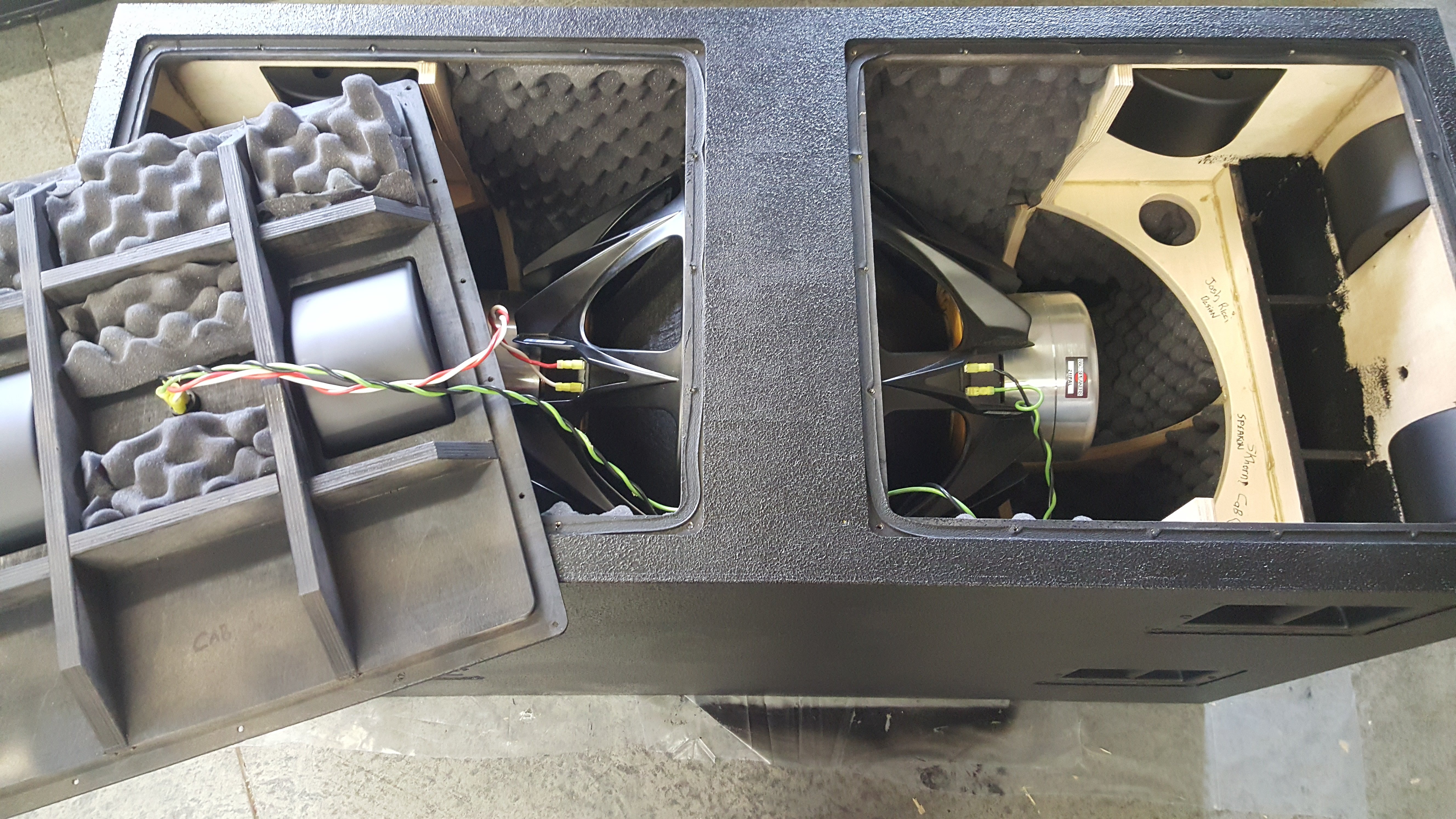
Yep... This is a 6th order BP type design. You don't want stuffing, just line the walls with some 1.5 or 2" / 50mm thick foam and staple gun it in there. Do the ported section only. All you are trying to do is knock down some of the high frequency reflections outside of the sub bandwidth. Try sticking your head inside of the unlined cab and snapping your fingers...There will be a lot of HF's and reflection. Repeat after lining and it's much much deader. Also it keeps the wire from rattling if they end up touching the cabinet wall. Keep the port entry clear though. A good 6" / 150mm clearance or so should be fine. See pics below. For a particularly nasty resonance you could put a pillow in there somewhere but it'll cut some efficiency and you must keep it away from the motor vents and the ports both. For calculating port tune I never include any extra length past the front plane of the port exit. When the exit is close to internal walls it will result in an apparent lengthening / deeper tune. This is where the extra apparent length comes from. See the line through the middle of the port section in the sketch below. Sometimes I use a radius in the corner in place of the straight angle, but this way is slightly more conservative. This is how I calculate them in cases like this. No extra length beyond the external exit. There is an extra few cm beyond the internal exit due to the back panel. A 45deg angle seems to approximate this length well based on measurements.


-
Making the cabs smaller will reduce the efficiency and sensitivity a little. Should not affect the FR shape or extension much. It's only 10mm. Make sure you check that the driver will still fit after subtracting 10mm though. A 21" driver frame is already very tight in this box width. Have you thought about adding a bit of extra wood to hold the grilles instead of modifying the cab width? I'm interested in seeing what you have going on with the steel baffles too. Good luck! I will see if I can get a hold of Kyle about your picture bandwidth questions.
-
With 726cm of vent area and 35m/s max velocity, port compression should be minimal. If I had to guess I'd say about 2dB port compression and that is only at maximum output. Reducing the output 3dB does wonders. I hope no one is running cabs at maximum! If you do you need more cabs. Airspeed will grow with the lower tuning options. There is nothing that can be done about it due to the physics. Have you read Collo's works and the JBL whitepapers on ports? One take away is that larger vent area will support larger air speeds with less chuffing and compression. With the modern high power drivers and tendency towards more compact enclosures it is impossible to keep vent velocities low. Especially with the low HT type tunings. The only way to do it is to make the enclosure unreasonably large, or limit SPL. Some of the speakers I've tested simulated to have >60ms velocity at maximum output. Some are approaching 100ms in the sims. More than a few of them actually. The cabs still work but a large amount of compression and noise is expected near max output.
-
This...
-
Sort of but it's more complicated than that. HR considers each boundary an infinite wall. This isn't true even with a bunch of cabs outdoors.
-
Hey Kipman... the port area listed is exactly what the area of the vents are. There is no fudge factor. Your calculation must be off a bit. 24" width, two 18mm side panels and three 12mm vent dividers. Length is 102cm effective calculated off of the sketches inside of Solidworks. Of the port calculation styles you linked only the 3rd and 4th from the left are worth using. Mixing #3 and #4 is worthwhile. The rest are inaccurate. I've designed, built and tested a bunch of designs with similar ports and that's how I've determined what results in a close match. Use #3 from the attachment for most cases.
-
Also that's a bunch of BLUE subs!
-
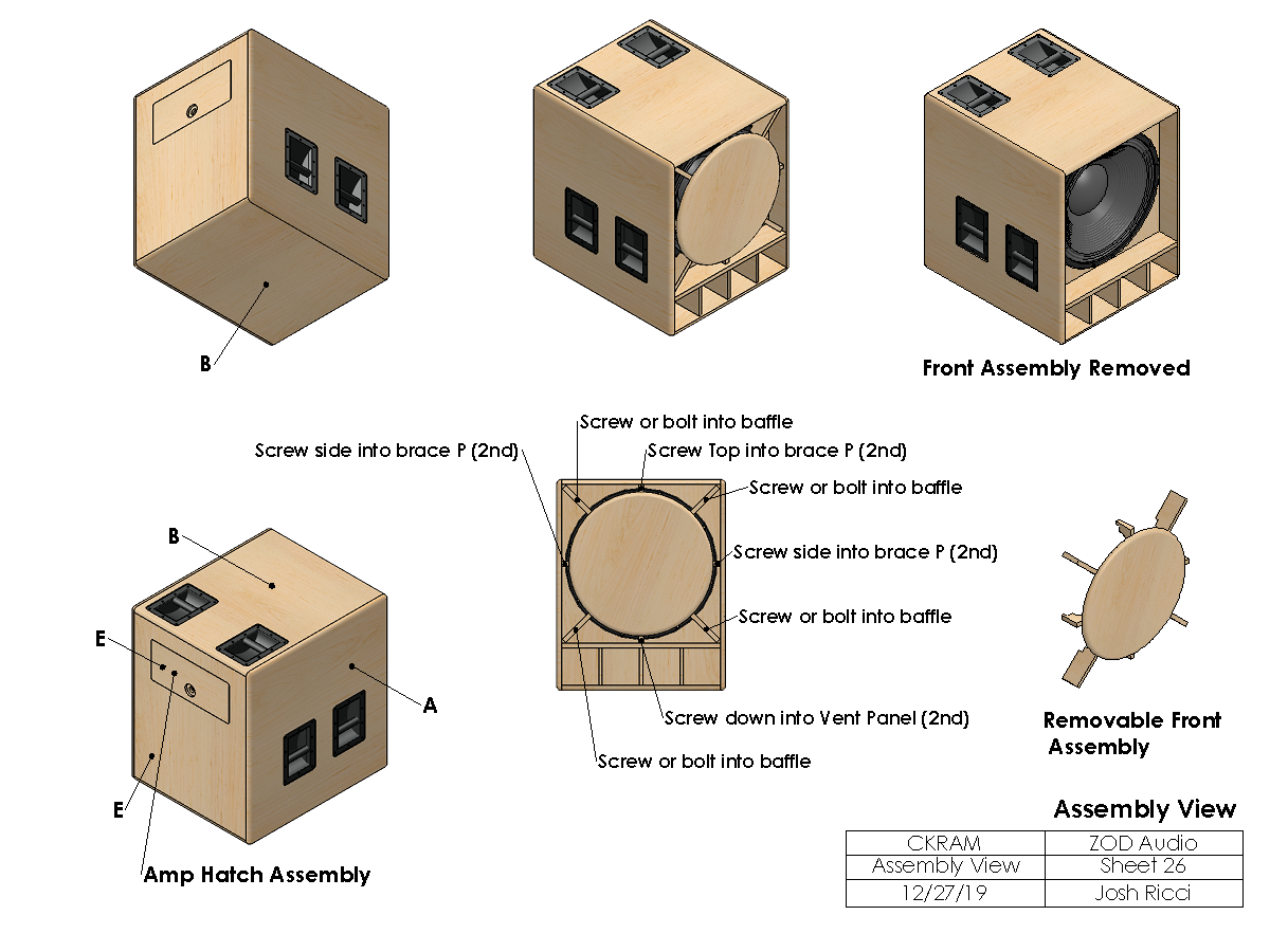
The primary mechanism will be 8 bolts into the baffle face with inserts, or screws could be used. 3 other screws would come into the end grain of the cover struts. 1 each through the 2 sides and the top. The holes would be pre-drilled to avoid splitting. A 4th would be pre-drilled and run at a 45deg angle into the vent panel. The main holding force would be the fasteners into the baffle. The other 4 screws would mainly be to keep those 4 struts from vibrating. As shown here.

-
I already factored in the extra proximity effect when I made my comments. That panel will need to be about 26cm to get the effective vent length in the sim. Looks like it is about 18 -20cm at most. Port bracing should always be accounted for. It reduces your effective vent area and multiple vents also tune a little higher than one big vent. At the end of the day we are probably talking a difference of a few Hz difference in the tuning, but even that can make a difference. S1 starts at the wall where the panels pinch together. Do you have 8 or 9 cm there before getting to the driver? Parallel wiring with speakons depends...You have a few options. You could make a splitter Y cable and run a speakon to each cab direct from the amp. You can also put 2 jacks on a cab and wire the second jack in parallel and use it to daisy chain to a second cab. This is much more common.
-
Do you still have the SKRAM? I'm interested. I need to get one to test.
-
I think you are the first person who has said that the chest pound is missing. Is it possible that what you are looking for is occurring in frequencies that are above the sub band? What some guys would refer to as the MBM range (100-200Hz) Are you using them outdoors, at home, big venues? Is it possible that you have acoustics issues contributing?
-
A couple of things that I see to double check. Not sure the horn section has 133cm of length? It's a little hard to judge from the drawing scale. Could be close. Also seems like the L12 length of 37cm is possibly a little too long. SKRAM is 28cm. Is there an extra 9cm length there? Again hard to tell for sure from the drawing. I think you may need 2 or 3cm more on the overall height to get the overall volumes in the sim. Depends on bracing, etc... though. Vent doesn't look long enough to effectively be 96cm to me? Based on your dims and port area provided the panel that connects at 90deg to the main vent panel would need to be about 26cm long to make a 96cm effective vent length.
-
I use the Voxengo spectrum analyzer as an investigative tool for mixing sometimes. How is the delay plugin?
-
Thanks for letting us know. At least you tried.
-
Yes. It's not that the LW1400 would not work, but it would not be my first choice and I would want to be careful with the overall volume until figuring out what it could take.
-
It's probably not a huge issue but I have seen a number of drivers with large shifts from coil center. Some were current drivers. I left a JBL 2269H sitting on it's face with 700g+ of magnets on the cone for a year to get it back to center rest position. It was probably 5 or 6mm inwardly set when I got it. It can and does happen. Back in the day it was probably a bigger issue with much shorter xmax and looser suspensions. On a modern woofer with 15mm xmax and a really tight suspension an offset of 1 or 2 mm isn't a big deal. Be more careful on drivers with a softer suspension, shorter xmax and heavier MMS. If the woofer takes a big offset it will still play but the sound may be degraded somewhat and the functional xmax shortened. If you can't hear it does it matter though...? I guess my point was ideally you'd keep the driver vertical, but sometimes the tradeoffs for that outweigh a horizontal driver position. I wouldn't worry about it too much. It's way down the list of priorities IMO.
-
LW1400 has a cone that is rather light and flexible for a 21". I'd be careful putting it into a cabinet which increases the pressures on the cone. S1 has a marginal impact in this type of design. Whether 300cm or 30cm. I wouldn't worry about it much. Especially at the cost of making the cab heavier or more complex.
-
Should be fine. They are more similar than different. This one just has much less path length and gain from the front section to keep the size down.
-
Not sure yet. Likely to be better than a direct radiator but not as good as my other designs since the driver is so close to the exits and visible from some angles.
-
That's one of the tradeoffs of this arrangement. Could always flip them once a year.
-
Have you considered an arrangement similar to this?
-
Droogne, Since you have additional height you can work with, that helps immensely. 60x65x100cm should be enough for a hybrid 6th or whatever these are called lately. Keep your HR sim at about 285L and you should be in the ballpark. Keep in mind that air volume is limited and any volume taken up by the front section has to come from the back section and the ports. A bigger front section= less low bass / higher vent velocities, but can produce more upper and middle bandwidth output and lower air velocity in the front section A bigger ported chamber and ports is the exact opposite = More low bass, lower vent velocity, less upper and middle bandwidth gain from the front section, higher front section velocity. Trying to find a good balance in smaller cabs can be a PITA, but it's possible. I'd recommend using all 5 horn sections. Even if it doesn't seem like the design needs to at first. Sometimes the extra section helps. Leave S1 where you have it. S2 is also good. 320-350cm is typical for the cross section of area at the center of a back mounted 21" pro woofer. Add that into your S2 like recommended earlier. S3 move to the end of the driver cutout like Peniku8 suggested. In a way this treats the air inside of the driver cone profile as part of the horn. It helps match the measured performance closer. You'll often see that there is a negative expansion from S2 to S3 because of it. If you had went from a larger S2 (after factoring in the 350cm in the driver cone) all the way out to your current S3 it would have made the apparent volume of that horn section much larger than it actually would be and the sim would reflect that. S4 I'd move this to your current S3 S5 Add this in for the last section from the current S3 location to the mouth. This way if you wanted to you could have a different angle on the 4th section versus the 3rd section. Triple check your hatch ideas and clearances for the driver. Consider how difficult it will be to get the driver in or out and how big of a problem it will be if there is an issue with the mounting bolt that is in the worst spot. Give yourself a little extra room. Where would your hatch be on the design above? Double side hatches? What if you wanted to switch to different drivers someday? Is there room for a driver that may be a few cm deeper? Also consider how prone to resonance or vibration the area around the driver will be. Hatches, etc...That outer panel in front of the cone on your diagram will be taking a hammering. How will this area be braced effectively while still clearing maximum driver excursion? One good way with this type of layout is to sit the outer panel in front of the driver on the ground. Not sure there is room for that in a 60-65cm foot print without getting fancy though.
-
Lucky dog! Quite the "toy" collection there.
-
Since the 21DS115 is 2.2 ohm DCR I usually do consider it as 2ohm nominal. Voltage sensitivity is a tricky subject since speaker cab impedance is all over the map. Still useful but not as much as many make it out to be IMO. With that said I was trying to maintain 95ish dB at 30Hz from this cab with nominal 1W voltage. The size makes it difficult. The Edge sim was for a single cab. I threw it together quickly. A mirrored cab shows about 1dB of gain at 40Hz another 1dB over the single cab by 70Hz and an additional 1.5dB 100-200Hz.